OpendTect plugins

Intro | Concept | The Tutorial plugin | Help Doc Creation | Installation and auto-loading

Intro

Background

Making your own software within OpendTect is in principle pretty easy. You could change the software by modifying existing classes and functions, and adding your own stuff to the libs. The advantage is total control. The problem with this approach, however, is that you have to keep the OpendTect sources in sync with new releases. Furthermore, if you cannot convince the opendtect.org people to also make those changes, OpendTect users may not be happy with your work.

An easy way to overcome this is to make your own plugins. Plugins make use of all the facilities of OpendTect but are loaded at run-time and can therefore be developed in a completely independent way. If you then find things that can't be done without modifying the OpendTect environment, it should be much easier to convince the opendtect.org people to take over or even implement those things themselves.

One thing you cannot do, is use another compiler than gcc/g++ on Linux/Mac or VC++ on Windows. OpendTect is built with it, if you want to use another compiler (why?) you'll have to make all libs and supporting libs (Qt, OpenSceneGraph) yourself. The make itself should be pretty easy to get started, but there will probably be some porting to do, too.


The concept

Dynamic loading

All modern Operating systems nowadays have ways to dynamically load libraries into a running program. The basic idea is:

  • Open the library
  • Query the contents for a certain routine using a string key
  • Call the routine returned
  • The routine then does the things needed to make itself useful.

As an example, a 'hello world' program could conceptually look like this:


dynlib = OpenDynamicLib( "libc.so" );
PrintfTypeFunction fn = (PrintfTypeFunction)GetDynLibFn( dynlib, "printf" );
fn( "Hello world\n" );

In this very simple case calling the function has no other effect than printing a string. In OpendTect, you'd want to add an attribute, create a menu item in the Opendtect menu, start horizon tracking, that sort of thing.

OpendTect plugins

In OpendTect, all of the dynamic lib querying etc. is already programmed. A plugin just needs to contain a few standard functions that will be called automatically when the dynamic library is loaded. There are three functions, of which only one is really required. Let's say the name of the plugin is MyMod, these functions will be:

GetMyModPluginType
GetMyModPluginInfo
InitMyModPlugin

Only the last one is required. The first one, Get...PluginType determines whether the plugin can be used for the auto-load, and if so, when. 'When' means: before or after the program has created the OpendTect GUI objects (and always after the static objects are initialized). The second function simply provides info for the users of your plugin.

An important remark here is that CMake supports plugin generation fully when the subdirectory name is the same as the plugin (base-)name. Thus, subdirectory MyPlugin generates libMyPlugin.so (or libMyPlugin.dylib or MyPlugin.dll) which should contain an InitMyPlugin() function.

Anyway, after typing make the plugin should be generated. The new plugin can be loaded from within OpendTect (Menu Utilities-Plugins; press the 'Load new' button).

Macros to define the required functions

There are macros available to define the plugin functions. They make it easier to read and maintain these functions. They are in odplugin.h. You'll use 2 of them for late (UI) plugins, 3 for early:

  • mDefODPluginEarlyLoad(PluginName)
  • mDefODPluginInfo(PluginName)
  • mDefODInitPlugin(PluginName)

See the Tutorial plugin code for example.

The Tutorial plugin

Intro

We have created the Tutorial plugins that you can find in your work environment. As is common in OpendTect, there is a plugin 'Tut' for non-ui, real-work stuff, and the 'uiTut' for the GUI part.

The idea of the tutorial plugins is to show a variety of common things that one might want to do, rather than make something useful for end-users. For that we'll make the following tools:

  • Manipulating some seismic data (read, process, write)
  • The same, but now using an Attribute
  • Do some work with horizons
  • Do some work with wells

In the process, we'll see how to:

  • Create menu items and toolbar icons
  • Make right-click tree item menus
  • Work in the OpenSceneGraph 'vis' world
  • Work with DataPack's and create flat displays

The uiTut plugin

In uiTut, the GUI consists of two parts. One deals with opening an independent dialog box via a menu item in the 'Utilities' menu. The other part gets the 'Tutorial' attribute listed in the 'Edit Attributes' dialog and creates the input fields in the same dialog box. It also sends the input parameters to Tutorial for attribute computation

Let us first have a look at the independent dialog part which in turn has two parts -- one for seismic tools and the other for horizon tools. The only interesting part is the uiIOObjSel class which allows you to select an item from a set -- a horizon or a seismic cube ( subclass uiSeisSel is used for seismic cube selection).

Both uiSeisTools and uiHorTools use the class uiTaskRunner, which triggers the Executor's in the Tut plugin. The class uiTaskRunner also displays a progress bar which keeps the user informed about the progress of the process.

Now we come to the attribute part. In the uitutorialattrib.cc file we see that although uiAttrDescEd is not a uiDialog like the the uiHorTools, it still is a valid parent (being a uiGroup) for the various UI elements. A nice feature of OpendTect is clear from the first line in the constructor: the inpfld is a special Attribute UI class which is handled just like any pre-defined uiBase or uiTools class. This illustrates that in the OpendTect GUI system, not only pre-made GUI elements are 'first class' - new objects with different shape and behavior attached will be usable transparently by any other GUI class.

Coming to the plugin 'main' file uitutpi.cc, like any typical UI plugin, uiTut is a LATE plugin, which means that it will be loaded only after the rest of the UI is already in place. Thus, you must not put mDefODPluginEarlyLoad().

Then comes the second 'special' plugin function GetxxxPluginInfo(). You may want to refer to the definition of the class PluginInfo for a better understanding of the above function. It allows the plugin manager to make this info available to the world.

mDefODPluginInfo(uiTut)
{
    DefineStaticLocalObject( PluginInfo, retpi,(
        "Tutorial plugin",
	"OpendTect",
	"dGB (Raman/Bert)",
	"3.2",
	"Shows some simple plugin development basics."
	    "\nCan be loaded into od_main only." };
    return &retpi;
}

And the last 'special' function is the one which gets things going:

mDefODInitPlugin(uiTut)
{
    mDefineStaticLocalObject( PtrMan, theinst_, = 0 );
    if ( theinst_ ) return 0;

    theinst_ = new uiTutMgr( ODMainWin() );
    if ( !theinst_ )
        return "Cannot instantiate Tutorial plugin";

    uiTutorialAttrib::initClass();
    TutHelpProvider::initClass();
    return 0;
}

The Tut plugin

The responsibility of uiTut is limited to talking to the user and getting the input parameters. The real work is done behind the scene by the non-UI Tut plugin. And that is the reason why it is of type EARLY. This particular plugin tells OpendTect's application manager that it wants to be loaded early - i.e. before any build of tables, data structures or user interfaces are made. That is typical of 'Real Work' plugins. The alternatives are NONE (which is very uncommon) and LATE, which is typical for UI plugins that want to start working when all objects have already been created. In this case, we need to specify that we have an EARLY plugin:


mDefODPluginEarlyLoad(Tut)

SeisTools

Let us first look at the direct seismic operations, that are handled by the class SeisTools, which in turn is a subclass of class Executor. 'Real work' is done by the function nextStep() which is typical of class Executor. Here, three different operations are possible: Scaling, where you can multiply the data values by a certain factor and apply a shift; Squaring, where, as the name suggests, you can take a square of the data values; and Smoothening, where you can take the arithmetic average of 3 or 5 samples depending on the filter strength. Traces are read one-by-one by a SeisTrcReader and supplied to the function handleTrace() where the actual computation is done. Then a SeisTrcWriter writes the output traces one-by-one to the output cube.

int Tut::SeisTools::nextStep()
{
    if ( !rdr_ )
        return createReader() ? Executor::MoreToDo()
	                      : Executor::ErrorOccurred();

    int rv = rdr_->get( trcin_.info() );
    if ( rv < 0 )
        { errmsg_ = rdr_->errMsg(); return Executor::ErrorOccurred(); }
    else if ( rv == 0 )
        return Executor::Finished();
    else if ( rv == 1 )
    {
        if ( !rdr_->get(trcin_) )
	    { errmsg_ = rdr_->errMsg(); return Executor::ErrorOccurred(); }

        trcout_ = trcin_;
	handleTrace();

        if ( !wrr_ && !createWriter() )
	    return Executor::ErrorOccurred();
	if ( !wrr_->put(trcout_) )
	    { errmsg_ = wrr_->errMsg(); return Executor::ErrorOccurred(); }
    }

    return Executor::MoreToDo();
}

Scaling and squaring are single-sample operations. But as you can see in the implementation of the function handleTrace() below, smoothening involves multi-sample computation. It requires separate input and output traces. Otherwise, if we did the operation on the same trace, we would be taking the modified values of samples preceding the current sample. For the sake of simplicity, we make a copy of the input trace to store the output values. This is not a good practice as it results in duplication of data. But since it is a tutorial, our aim is to keep the code as simple as possible and leave the efficiency part for serious programming.

void Tut::SeisTools::handleTrace()
{
    switch ( action_ )
    {

    case Scale: {
        SeisTrcPropChg stpc( trcout_ );
	stpc.scale( factor_, shift_ );
    } break;

    case Square: {
        for ( int icomp=0; icomp < trcin_.nrComponents(); icomp++ )
	{
	    for ( int idx=0; idx < trcin_.size(); idx++ )
	    {
	        const float v = trcin_.get( idx, icomp );
		trcout_.set( idx, v*v, icomp );
		}
	}
    } break;

    case Smooth: {
        const int sgate = weaksmooth_ ? 3 : 5;
	const int sgate2 = sgate/2;
	for ( int icomp=0; icomp < trcin_.nrComponents(); icomp++ )
	{
	    for ( int idx=0; idx < trcin_.size(); idx++ )
	    {
	        float sum = 0;
		int count = 0;
		for( int ismp=idx-sgate2; ismp <= idx+sgate2; ismp++)
		{
		    const float val = trcin_.get( ismp, icomp );
		    if ( !mIsUdf(val) )
		    {
		        sum += val;
			count++;
			}
		}
		if ( count )
		    trcout_.set( idx, sum/count, icomp );
		}
	}

    } break;

    }

    nrdone_++;
}

HorTool

Similar to SeisTools, HorTool performs some simple operations on horizons: thickness computation and smoothening. Each of these operations is handled by a subclass of HorTool which is a subclass of Executor and as expected the computation is performed by the function nextStep(). You may notice here that no object of class HorTool is defined anywhere. It is only used as the base class for classes ThicknessCalculator and HorSmoothener. Let us have a look at the nextStep() function in class ThicknessCalculator to see how the data values are accessed in a Horizon3D:

int Tut::ThicknessCalculator::nextStep()
{
    if ( !iter_->next(bid_) )
        return Executor::Finished();

    int nrsect = horizon1_->nrSections();
    if ( horizon2_->nrSections() < nrsect ) nrsect = horizon2_->nrSections();

    for ( EM::SectionID isect=0; isectgetPos( isect, subid ).z;
	const float z2 = horizon2_->getPos( isect, subid ).z;

        float val = mUdf(float);
	if ( !mIsUdf(z1) && !mIsUdf(z2) )
	    val = fabs( z2 - z1 ) * usrfac_;

        posid_.setSubID( subid );
	posid_.setSectionID( isect );
	horizon1_->auxdata.setAuxDataVal( dataidx_, posid_, val );
    }

    nrdone_++;
    return Executor::MoreToDo();
}

Please note the difference in the function dataSaver in the two classes. In ThicknessCalculator, it saves the auxilary data, whereas in HorSmoothener, it saves the geometry.

The Tutorial Attribute

We have seen the direct seismic approach to simple operations on seismic data in SeisTools. For our purpose, it suits well. But the main problem with this approach is the difficulty in multi-trace handling. Moreover, for large seismic volumes, handling each trace one-by-one may slow down the process. This brings us to another approach called Attributes. In this example, we define the Tutorial attribute to do things once done by SeisTools. As we discuss different aspects of making an attribute, we will also discuss its advantages over the direct seismic approach.

The main plugin file "tutpi.cc" makes a call to Tutorial::initClass(). The class Tutorial ( tutorialattrib.h ) is defined as a subclass of Attrib::Provider class. Every attribute is a provider, each can thus be used as input for another attribute.

Steering

A Steering cube, as the name suggests, works as a guiding cube. It stores the Inline dip and Crossline dip at each point, which guides the attribute engine in multi-trace computations. In case of our Tutorial attribute, we can use the steering data for horizontal smoothening. The key function is initSteering() which makes the steering data available in the form of shifts relative to the central trace. To understand how this shift is used during computation, please refer to the horizontal smoothening section in the function computeData().

Some fundamental attribute functions are listed here:

createInstance()

This function is standard for every attribute, here is the attribute constructor called. Use the macro mAttrDefCreateInstance to define createInstance:

mAttrDefCreateInstance(Tutorial)

initClass()

This static function initializes the attribute: sets up the parameters and the number and type of the inputs and outputs. You can compare this to what you see in Opendtect in the attribute definition window after loading the uiTut plugin.

If you look at the parts of the implementation carefully, ( tutorialattrib.cc ) you'll see that each parameter is built up following this example:

EnumParam* action = new EnumParam( actionStr() );
    action->addEnum( "Scale" );
    action->addEnum( "Square" );
    action->addEnum( "Smooth" );
    desc->addParam( action );

Every parameter is required by default, to overrule this use setRequired(false)"

initClass() also adds the attribute to the attribute factory. In this case, as every attribute is a provider, the Tutorial attribute is added to PF() (the Attrib::ProviderFactory singleton access function).

updateDesc()

Will be used not only to update the parameters but also the number and type of the outputs and to add or disable some inputs. If you look at the implementation for the tutorial attribute, this function just allows to enable or disable the inputs ( factor, shift and smooth ) according to the action chosen by the user

getInputOutput()

we need to define this initialization function because we have Steering. Steering always carries two outputs and we need them both.

initSteering()

If we are using steering data, this function prepares the steering input for use in computation. A subvolume is generated around the central trace, with the size of the subvolume specified by the stepout. This data contains the shifts in terms of number of samples for each trace in the subvolume relative to the central trace.

void Tutorial::initSteering()
{
    if ( inputs[1] && inputs[1]->getDesc().isSteering() )
        inputs[1]->initSteering( stepout_ );
}

getInputData()

Before the work can be done, some input has to be given. This function is the place where you specify how to get your input data. For the Tutorial this is the seismic data. But it can also be Steering Data or any other attribute.

bool Tutorial::getInputData( const BinID& relpos, int zintv )
{
    if ( inpdata_.isEmpty() )
        inpdata_ += 0;
    const DataHolder* data = inputs[0]->getData( relpos, zintv );
    if ( !data ) return false;
    inpdata_.replace( 0, data);


    if ( action_ ==2 && horsmooth_ )
    {
        steeringdata_ = inputs[1] ? inputs[1]->getData( relpos, zintv ) : 0;
	const int maxlength  = mMAX(stepout_.inl, stepout_.crl)*2 + 1;
	while ( inpdata_.size() < maxlength * maxlength )
	    inpdata_ += 0;

        for ( int idx=0; idxgetData( relpos + posandsteeridx_.pos_[idx] );
		if ( !data ) continue;
	    inpdata_.replace( posandsteeridx_.steeridx_[idx], data);
	}
    }

    dataidx_ = getDataIndex( 0 );

    return true;

}

You will notice from here that the calculation of the attributes is not done on traces but using a different object, the DataHolder. The dataholder contains a set of ValueSeries which holds the value of every sample of the SeisTrc. Advantage: in case of an attribute which has other attributes as inputs, data is available in the corresponding dataholders, it thus saves a lot of time ( easier and much faster to read some floats in a ValueSeries than to get values from a SeisTrc ). Stored data are read from cubes of seismic traces and written the same way.

The DataHolder is also carrying some specific information about the trace to be processed, like the start sample number and the number of samples you wish to calculate.

Another important remark: calculation is made using sample numbers, not time or depth

Most of the rest of the methods are there to comply with the Attrib::Provider interface - see the Attrib::Provider documentation. The basic idea is that for each sample of each trace one or more attribute values can be calculated. The number of attribute values (or outputs) is defined in the initClass() function. If your input requires additional samples (timegate) or neighbouring traces (stepout), you will have to define reqZMargin() and reqStepout() respectively.

computeData()

When we want to look at the actual work, the place to be is the computeData() method. This is the place where you define the mathematics for calculating the attribute. This function is called for each trace of your output cube.

In the computeData() method, we are faced with a number of Z ranges. To be able to support multi-threading, computeData must be ready to only process part of the trace. Then, also, we can have input cubes that are larger than requested or desired, or smaller than that. This delivers a rather nasty picture of Z indexes that we really cannot circumvent. To make things at least clear, the indexes are all related to the the absolute Z=0. This is where everything refers to. Then, we have different start Z indexes for each of the input cubes and the output cube. These are named 'z0_' in the corresponding DataHolders.

Explaining Z0

Let us have a look at the Tutorial::computeData function and compare it with the code in SeisTools. The algorithm for actual computation is the same in both the cases, but there is a marked difference in the manner in which seismic data is accessed in each case.

bool Tutorial::computeData( const DataHolder& output, const BinID& relpos,
                           int z0, int nrsamples, int threadid ) const
{
    for ( int idx=0; idx < nrsamples; idx++ )
    {
        float outval = 0;
	if ( action_==0 || action_==1 )
	{
	    const float trcval = getInputValue( *inputdata_, dataidx_,
	                                        idx, z0 );
						outval = action_==0 ? trcval * factor_ + shift_ :
	                                trcval * trcval;
					}
	else if ( action_==2 && !horsmooth_ )
	{
	    float sum = 0;
	    int count = 0;
	    for ( int isamp=sampgate_.start; isamp <= sampgate_.stop; isamp++ )
	    {
	        const float curval = getInputValue( *inpdata_[0], dataidx_,
		                        idx + isamp, z0 );
					if ( !mIsUdf(curval) )
		{
		    sum += curval;
		    count ++;
		}
		}
	    outval = sum / count;
	}
	else if (action_ == 2 && horsmooth_ )
	{
	    float sum = 0;
	    int count = 0;
	    for ( int posidx=0; posidx < inpdata_.size(); posidx++ )
	    {
	        if ( !inpdata_[posidx] ) continue;
		const float shift = steeringdata_ ?
		        getInputValue( *steeringdata_,posidx, idx, z0 ) : 0;
			const int sampidx = idx + ( mIsUdf(shift) ? 0 : mNINT(shift) );
		if ( sampidx < 0 || sampidx >= nrsamples ) continue;
		const float val = getInputValue( *inpdata_[posidx],
		                        dataidx_, sampidx, z0 );
					if ( !mIsUdf(val) )
		{
		    sum += val;
		    count ++;
		}
		}
	    outval = sum / count;
	}

        setOutputValue( output, 0, idx, z0, outval );
    }

    return true;

}


Creating the Help Documention

The help system

Like any other commercial application, our plugin also needs a help document which a user can see by clicking on a button in the user interface. The OpendTect help system is quite flexible and allows a plugin to define its own way of showing help information. But in most cases all you want is to open an HTML file either stored locally or on the web. For this purpose we have a class called SimpleHelpProvider that provides a key-link based help system. The idea is to have a common base URL (can be a local file path) and then append links for individual help documents to this base URL, based on keys.

So, you need to define your own HelpProvider class as a subclass of SimpleHelpProvider and initialize it when the plugin loads. A good example is the TutHelpProvider defined in uitutpi.cc:

class TutHelpProvider : public SimpleHelpProvider
{
public:
TutHelpProvider( const char* baseurl, const char* linkfnm )
    : SimpleHelpProvider(baseurl,linkfnm)
{}

static void initClass()
{
    HelpProvider::factory().addCreator( TutHelpProvider::createInstance, "tut");
}

static HelpProvider* createInstance()
{
    FilePath fp( GetDocFileDir(""), "User", "tut" );
    BufferString baseurl( "file:///" );
    baseurl.add( fp.fullPath() ).add( "/" );

    fp.add( "KeyLinkTable.txt" );
    BufferString tablefnm = fp.fullPath();

    return new TutHelpProvider( baseurl.buf(), tablefnm.buf() );
}

};

The three key elements of this class are:

  • The provider key: 'tut' in this case.
  • The base URL: Here it is a local path inside the OpendTect installation. But it can as well be a web URL like 'http://doc.opendtect.org/'
  • The key-link table, which is read from a file 'KeyLinkTable.txt' here. But you can also make it on-the-fly using the function addKeyLink. That is rather convenient if you are doing it just for a couple of plugins.

Then in the UI you can use a HelpKey comprising of two parts: the provider key ('tut' for example) and the key for the individual UI, like 'hor' in uiHorTools:

uiTutHorTools::uiTutHorTools( uiParent* p )
        : uiDialog( p, Setup( tr("Tut Horizon tools"),
	                      tr("Specify process parameters"),
			      HelpKey("tut","hor") ) )

When the user clicks on the help button the HelpProvider will look for the link for the corresponding key, append the link to the base URL and open the document

Installation and auto-loading

Once you have made your own plugin, you probably would like it to be loaded automatically whenever OpendTect is started. OpendTect provides some facilities that do just that.

Preparing a plugin for auto-load

#include "odplugin.h" is needed for the PluginInfo structure and the PI_AUTO_INIT_xxx defines.

The GetxxxxPluginType() specifies when a plugin is loaded:

  • PI_AUTO_INIT_EARLY : Plugin is loaded before construction of main window
  • PI_AUTO_INIT_LATE : Plugin is loaded after construction of main window

The default is PI_AUTO_INIT_LATE, so you only have to define anything if the plugin needs to be loaded early: then use mDefODPluginEarlyLoad(YourPluginName).

Installing plugins for auto-load

The auto-load tool of OpendTect looks for plugins to load in two places:

1) Where are the .ALO files stored? The two locations searched are (in this order):

  • <userdir>/plugins/<platform_dir>
  • <systemdir>/plugins/<platform_dir>

2) Where are the plugin libraries? Locations are:

  • <userdir>/bin/<platform_dir>/[Release|Debug]
  • <systemdir>/bin/<platform_dir>/[Release|Debug]

The <userdir> is determined as follows:

  • If it is set, $OD_USER_PLUGIN_DIR
  • Else, the user settings directory is used: ~/.od

On Windows, your 'Personal directory' is located at $HOME if this is defined. Otherwise, $USERPROFILE is used. Also see the specific notes in the windows documentation.

Using .alo files

Auto Load files are simple text files that tell a program which plugins it is supposed to load from the 'libs' directory. Since OpendTect contains multiple programs, each program has its own set of .alo files '<program name>.*.alo', while the plugins can be shared between multiple programs. OpendTect will scan for any file with this naming convention. So od_main.john.alo is perfectly OK.

Since there are multiple vendors and/or plugin sets, each vendor can make his own .alo files. od_main, for example, will look at any file named od_main.*.alo. For this example, the default plugins are specified by od_main.base.alo, while dgb's plugins are specified by od_main.dgb.alo. This way, each vendor can make his own .alo files, without interfering with others.

A .alo file is nothing more then a simple list of plugins, without extensions. For example, this could be in an od_main.base.alo file:


Annotations
Madagascar
uiMadagascar
CmdDriver
GMT
uiGMT

Note that for each platform, a specific .alo file must be created. Usually, they will be the same, but some plugins might not be relevant or supported on all platforms.

The plugins in the .alo files are loaded in the order as specified in the file. The alo files themselves are handled in alphabetical order.


Distributing your plugins

The publishing and distribution of OpendTect plugins is pretty straightforward. The .alo files can be installed in the plugins/platform ($DTECT_APPL/plugins/$HDIR) directory, while the actual plugins (the .DLL, .so or .dylib files) go in the normal bin sub-directory.

On Unix, this means that you can make a tar.gz or zip file containing the plugins in a directory structure as described above, which can be extracted into the existing OpendTect installation directory.

On Windows this is also possible, but it is more common to use an auto-extracting installer to do this. For more info on this, see the windows documentation.

If you want your plugins to be used around the world, then you may want to contact support@opendtect.org to get your plugin(s) distributed via the OpendTect installation Manager. Be prepared to have the opendtect.org people take a look at your code and test the stability. Then make the packages along the lines described below. You'll also have to provide information about yourself and the plugin - and a picture of a certain size.

Preparing for the installation manager

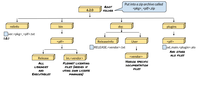
The general structure of a package is explained in the following diagram:

Explaining Package Structure

It is important that you make the packages nicely modular. Even if you have only two platforms yet, still it's a good idea to split the stuff in platform-independent and platform-dependent stuff. And separate documentation. In that case there would be 4 packages:

  • The platform-independent part (hidden for the user)
  • Part for platform 1
  • Part for platform 2
  • Documentation

The user will see only two: the plugin itself and the documentation.

Then the naming of the packages. Let's not make a big specification document; you can guess this by looking at what is now in the opendtect.txt file. Specifics:

  • We will need a similar package definition file (<vendor>.txt). That is the sort of info we need. Don't worry about the codes you see in there, just the basic info like descriptions and dependencies. That would allow us to make this file. You can deliver the whole file if you want to, but we can also maintain it.
  • Provide an image for each package you deliver and one for your company (vendor). The target size would be around 100x100 for the product logo and 16x16 for the vendor logo.
  • Make sure every package contains a file: <OpendTect version>/relinfo/ver.<package_name>[_plf].txt Like:
    6.4.0/relinfo/ver.jimsinversion_lux64.txt
    6.4.0/relinfo/ver.pppraytrace.txt

You can have your own version numbering, but it has to have this form:
number.number.number[optional_free_text_without_dots_starting_with_non_digit]
You are completely free in your numbering, and the optional text. The installer uses the '>' operator for every part. The numbers have to be integer numbers, and will be compared as integers.

Users cannot update a packages without also updating the packages that these are dependent on. This circumvents the need to specify exactly the dependencies on which versions on what other packages.


Index | Overview | Rules | Attributes | UNIX | MS Windows | opendtect.org