4.1 Background
Dip-Steering is defined as the process of following seismic reflectors by auto-tracking the pre-calculated dip-field from a given starting position. The pre-calculated dip-field in OpendTect is stored in a Steering-Cube, which contains two values at each seismic sample position: the dip in the inline direction and the dip in the cross-line direction.
Dip-Steering is a key concept in OpendTect that is used to:
- Compute dip-steered multi-trace attributes. Examples are: Similarity, Texture, Volume Statistics, … Also Neural Network-based ‘probability’ volumes such as ChimneyCubes and FaultCubes include many dip-steered attributes.
- Compute attributes directly from the Steering-Cube. Examples are: the set of Volume Curvature attributes and (geologic) dip and azimuth.
- Apply dip-steered filters. Examples are: dip-steered median filter and dip-steered fault-enhancement filter.
- Auto-track horizons. Examples are the HorizonCube auto-tracker which tracks thousands of horizons directly from the dip-field and OpendTect’s conventional amplitude and similarity tracker that can optionally include dip to constrain the tracker.
- Grid loosely mapped horizons. The dip-steered gridding algorithm fills in holes and unmapped parts to generate a horizon that exists at every seismic location.
Depending on the process it is often useful to work with more than one Steering-Cube. Typically, we use two Steering Cubes. The ‘Detailed SteeringCube’ contains dips as calculated by the dip-computation algorithm (OpendTect supports multiple algorithms, see …). The Detailed SteeringCube is used if we need to preserve details in the data, e.g. when computing Volume Curvature attributes in fracture detection studies. The ‘Background SteeringCube’ is a smoothed (usually median-filtered) version of the Detailed SteeringCube. The Background SteeringCube contains less noise and the dips follow larger structural trends. It is typically favoured for dip-steered filtering operations.
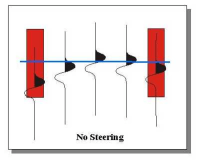
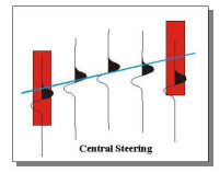
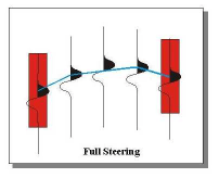
The Dip-Steering plugin for OpendTect supports two different modes of data-driven steering: Central Steering and Full Steering. In Central steering the dip / azimuth at the evaluation point is followed to find all trace segments needed to compute the attribute response / filter / track the event. In Full steering the dip/azimuth is updated at every trace position. The difference between 'no steering', 'central steering' and 'full steering' is shown in the following figures. Note that these figures show the 2D equivalent of steering, which in actual fact is a 3D operation.
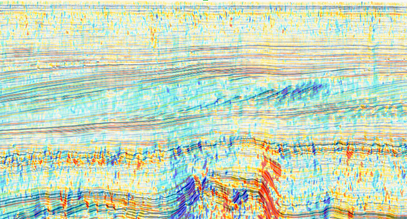
SteeringCube information can be displayed in a 3D scene directly from the OpendTect tree, in two ways, as shown in the pictures below. This option displays the cross-line dip along an inline, or the inline dip along a cross-line.

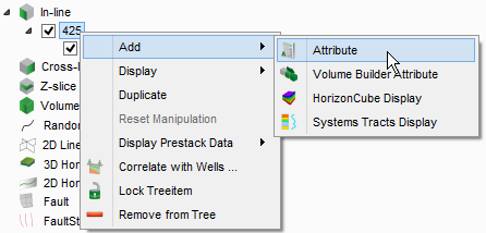
Detailed SteeringCube of inline 425 in F3-Demo. For display purposes the (cross-line) dip image was made (50%) transparent:
Dip-Steering options are launched from the Processing -> Dip Steering Menu. Dip-Steering is available for 2D seismic and 3D seismic. A SteeringCube for a 2D line stores at every sample position the dip in the line direction. A SteeringCube for a 3D volume stores two values per sample position: the dip in the inline direction and the dip in the cross-line direction.
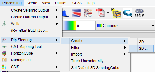
The windows pictured and described in this manual are the ones pertaining to 3D processing. 2D processing windows are similar and the same description can therefore be used for 2D dip-steering.
References
The following references are available from the dGB website. Although slightly out of date, the concepts are still valid: