5.2.1.7 Create 2D Seismic Lattice
This tool is used to create a 2D lattice/grid from 3D seismic data. This feature is released as a Multi2D workflow in the SSIS plugin (Chapter 7). The workflow is simple i.e. convert 3D seismic data into a coarse 2D grid with preferred orientation and geometry. After the conversion, the next step is to prepare a HorizonCube for all 2D lines. Using the HorizonCube for each 2D line, interpret sequence stratigraphic surfaces. The extracted sequence stratigraphic surfaces are then used to do detailed interpretations on the 3D seismic volume.
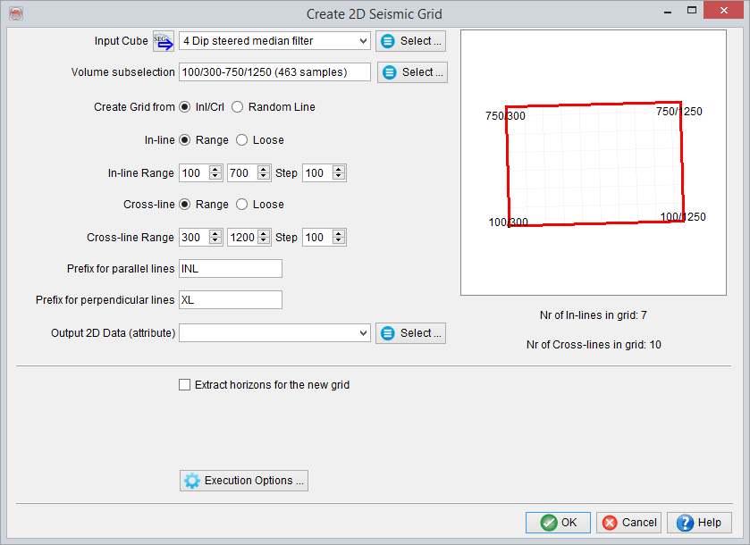
2D Seismic Grid options
- Input Cube: Selected 3D seismic data to be used in this field.
- Volume Subselection: Optionally, the 3D volume can be restricted to an objective area. This subselection is made here by restricting inline/crossline/time ranges for the selected volume.
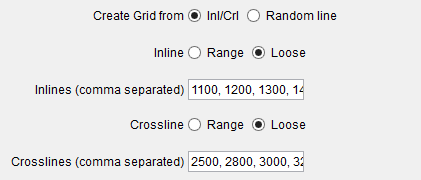
- Create Grid from: Define the output grid geometry and orientation of the 2D lines to be created. If Inl/Crl is selected for this option, the general inline/crossline orientation (or geometry) of the selected 3D data would be used within the defined inline/crossline range and the corresponding steps. Optionally, the inline/crossline range can be edited manually by setting loosely spaced inline/crossline numbers separated by commas.
Another option is to define a 2D grid geometry using a Random Line. Using the selected random line, the grid can be created in both (parallel and perpendicular) directions of the randomline. This fixed spacing needs to be given in the line spacing (m) fields.
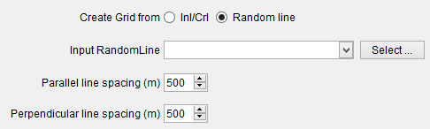
Random Line options
- Prefix: Label the 2D-line names in the fields.
- Output Lineset: Output for the 2D lineset. Please provide the lineset name and the name for the seismic data (attribute).
- Extract Horizons: Convert the 3D interpreted horizons into 2D horizons by checking this box (optional). In the Select horizons list, select one or more horizons.