8.4.1 Simple Wedge Model/Property Variations Using one Well
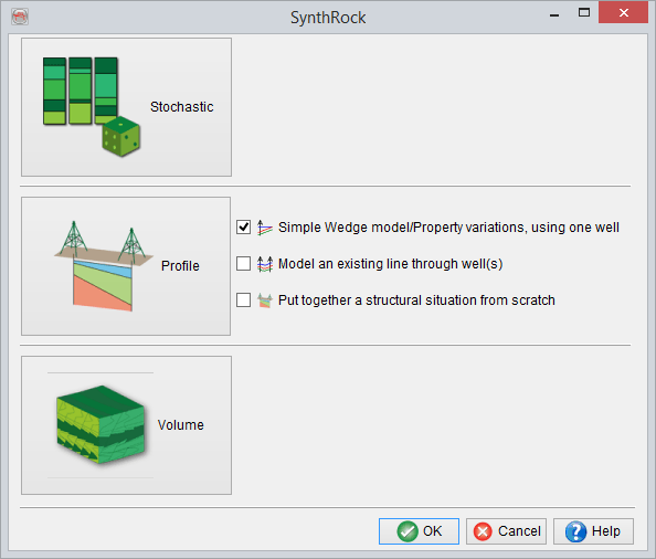
Simple Wedge model/Property variations, using one well is the first pre-defined workflow in SynthRock profile modeling which allows to quickly build a simple wedge model and/or model lateral property variations. It is launched by checking the corresponding box in SynthRock start window and clicking OK.
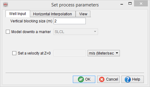
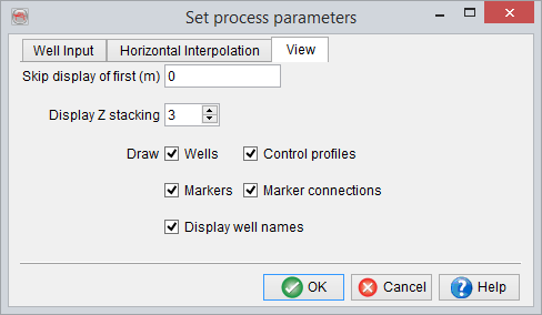
A user is expected to go through the pre-defined sequence of windows. The workflow starts, as any profile modeling in SynthRock, with setting modeling parameters in Set process parameters window and selecting properties to be modeled in Layer Properties - Selection window. Once the workflow is completed, both sets of parameters can be modified by clicking on![]() and
and ![]() icons of the Layer modeling window respectively.
icons of the Layer modeling window respectively.
In the example below, few changes of the default parameters are made in the first window in order to limit the modeled interval.
Porosity is added in addition to the default properties in the second window.

Once the modeling parameters and the property list are confirmed, Add well window allows to choose an existing well from a project database. In the example below F02-1 is selected. An attempt to automatically determine well logs matching the modeled properties is made by the software, but it is recommended to always confirm the correct logs are selected. Note, that all properties chosen in Layer Properties - Selection window are required to have a log selected. Missing logs can be either created by clicking on the ![]() icon without having to exit SynthRock or imported using Well Manager. Selected log can be displayed by clicking on the
icon without having to exit SynthRock or imported using Well Manager. Selected log can be displayed by clicking on the![]() icon.
icon.

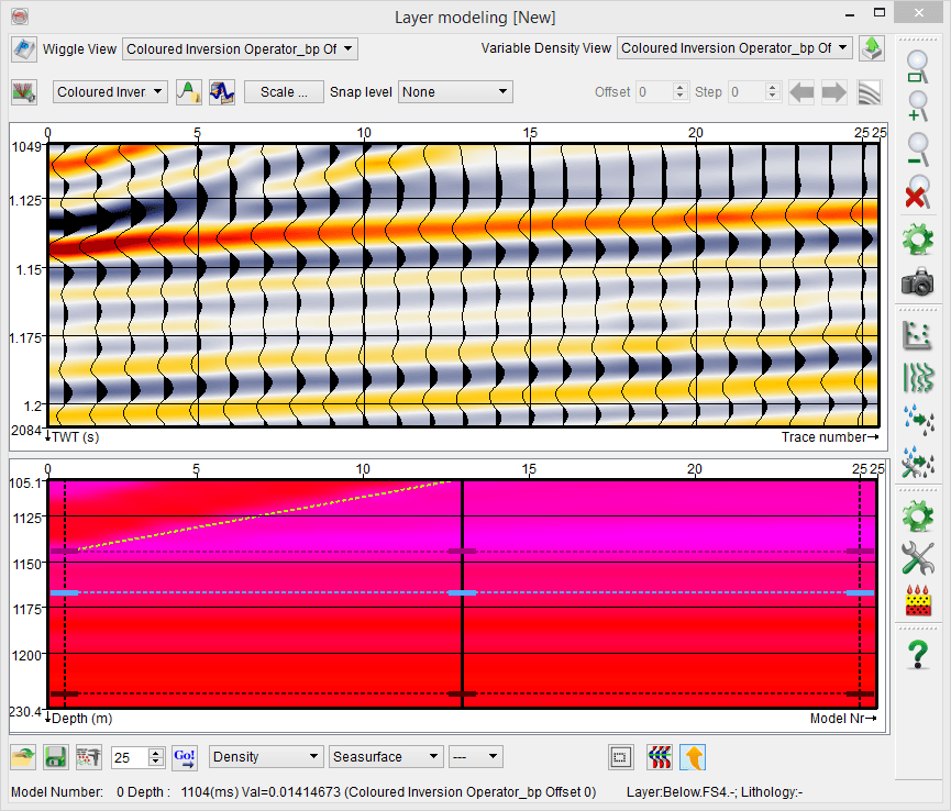
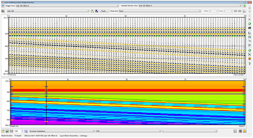
Before proceeding further observe changes in the Layer modeling window after clicking on the Apply button. A default number of pseudowells has been created, which are in fact simply duplicates of the selected well with logs upscaled according to Set process parameters window. The original well is positioned at the far-left side of the profile and displayed as a solid vertical line. The control profile is positioned at the far-right side of the profile and displayed as a dashed vertical line. Corresponding synthetic seismic section has been generated using the chosen wavelet and displayed in the top part of Layer modeling window.
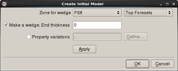
Clicking on OK button prompts to Create Initial Model window where a wedge thickness change and/or lateral property variations can be defined. First, a user must specify a zone by choosing existing well tops.
A wedge model
If thickness changes are modeled in the selected zone, Make a wedge option has to be checked, and End thickness, corresponding to the control profile at far right, has to be set. In the example below, wedge model of the FS8 - Top Foresets interval is defined by varying its thickness from the original value at the well (128 m) to 0 m. Clicking OK generates the defined model.
If property changes are modeled alone, Property variations option must be checked and Make a wedge option must be unchecked. Property variations have to be specified by clicking on Define button.

In Define property changes window, properties of a selected interval can be changed in such a manner that individual samples of a property are scaled to have the user-specified average in the given interval. The greyed-out left column contains initial average property values, and new average values must be specified in the right column. In the example below, Porosity is decreased to 5 percent with corresponding increases in Density and Pwave velocity. Click OK to confirm the changes.

The Create Initial Model window is updated as shown below. Click Apply or OK to generate the model.
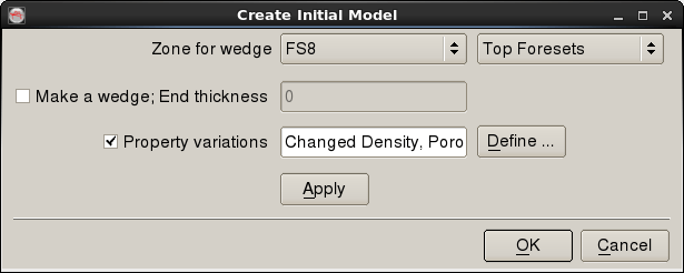

A wedge model with property variations
Finally, a wedge model can be combined with property variations by checking both options and defining the parameters as described above.