5.2.7 Voxel Connectivity Filter
Voxel Connextivity Filter is a special tool to create continuous bodies based on the amplitudes in a stored volume. A 'voxel' is defined as the volume around one sample. It is thus linked to the survey bin size and sampling rate.
This volume builder step must be preceded by a step providing the necessary input data, like "Stored volume".
This volume builder step implies a volumetric calculation. The result of the application on a single inline will differ from the result of the application to the whole volume.
The filter is based on a user-defined amplitude selection to compute the bodies. The samples interconnection is computed based on an amplitude criteria and geometrical spreading settings. It is a very useful tool to visualize seismic attributes in 3D. Other benefits of this tool are to get a volume of several bodies and visualize them in 3D or use it as an input to supervised Neural Network. A general and most popular use of this tool can be the DHIs detection. For instance, if creating a volume that represents DHIs only, it may be interesting to clip the amplitudes to visualize the DHIs present in the seismic data. For such case, when having the seismic amplitude attribute as a volume, this filter can be used to create new DHI volume.
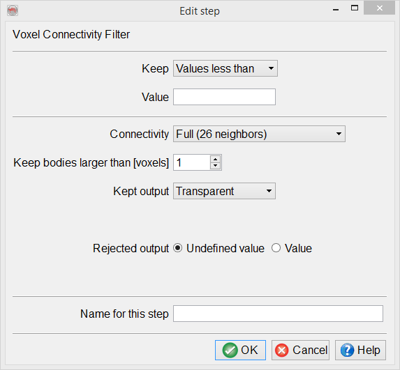
The voxel connectivity filter has a number of parameters to set:
Keep: Specifies the part of the input dataset used to compute the bodies, based on their amplitudes.
- Values more than: The envelope of the amplitudes higher than the given value define the bodies to be computed. Example: 0 will select all positive amplitudes.
- Values less than: The envelope of the amplitudes lower than the given value define the bodies to be computed. Example: 0 will select all negative amplitudes.
- Values between: The envelope of the amplitudes between inside the given range define the bodies to be computed. Example: 9000, 14000 will select all values in between, like 12000.
- Values outside: The envelope of the amplitudes between outside the given range define the bodies to be computed. Example: -10000, 10000 will select all values lower than -10000 or larger than +10000 (the extremes).
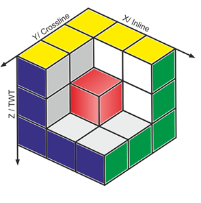
Connectivity: Selects the method used to connect different voxels when computing the bodies. Each sample in the input volume acts like a seed.
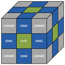
- Common Faces (6 neighbours): The propagation is done by strictly using the 6 faces adjacent to the current seed.
- Common Edges (18 neighbours): The propagation is done by using the 6 faces and the 12 edges adjacent to the current seed.
- Full (26 neighbours): The propagation is done is all directions, using the 6 faces, 12 edges and 8 corners adjacent to the current seed. This is the default mode.
The easiest way to visualize the connectivity is to imagine the reference voxel as the central voxel in a 3x3x3 cube, such as the red one in the first image. Then the second image shows the Face-, Edge- and Full (corner) conecctions:
Keep bodies larger than [voxels]: It defines the minimum number of voxels required to output a body. Actually all bodies are computed in the first pass. The smallest bodies are then dismissed. Minimum allowed is one.
Keep output: The following value(s) will be output on the samples inside the computed bodies:
Body-size rank:The output value is an integer with a constant, different value for each body. The values are sorted by decreasing body size, starting at zero: 0 is the largest body, 1 the second largest...
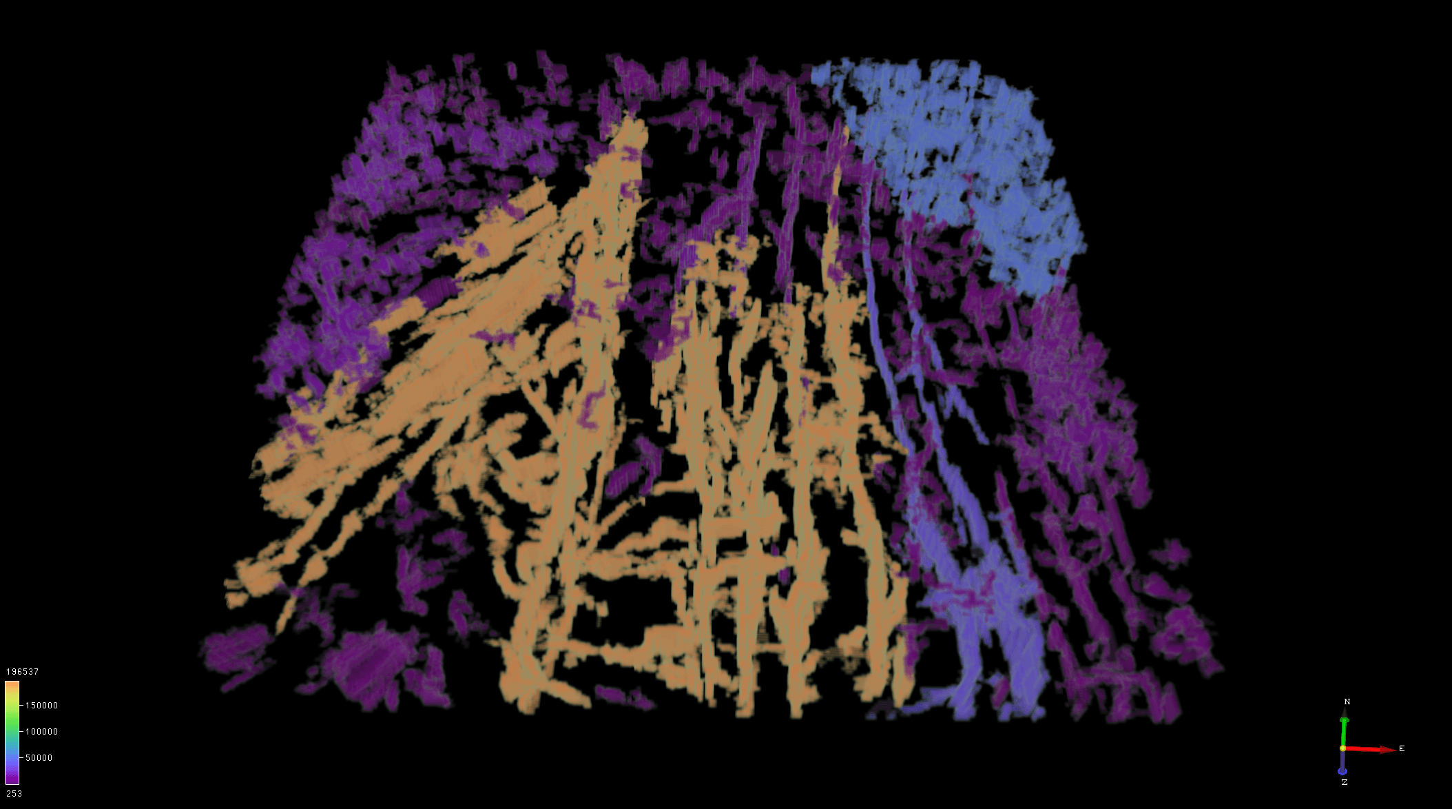
The example below is created using a similarity attribute to locate faults and fractures in a volume. It is set-up to create bodies connecting low similarity values (threshold of 0.5). All values that are above this threshold are ignored. Furthermore, it is also ignores the very small bodies (size < 10 voxels).
It shows number of connected bodies (purple being the largest ones) in a volume. Such a result can directly show which faults are connected and those that are not. Visualizing such a VCF result can be a valuable method in performing direct interpretation.

Body-size: The output value is the size in number of voxels of each body. This gives an approximation of the real-world volume, when multiplying by the bin size. For example, a body of 2500 voxels (10 inlines, 50 crosslines, 5 samples), with a bin size 25m x 12.5m, at 4ms sampling with a constant velocity of 2000 m/s: Vol = 2500 * 25 * 12.5 * 2000*0.004/2 = 10000 m3...
In this second example, the same volume is being processed for Body-size. It shows the same patterns suggesting that the prediction is identical to the earlier result. However, the predicted voxels are being filled differently. Here the same bodies are defined by largest volume in cubic meters (m3).
Generally speaking, areas of higher faults/fractures density allow greater connectivity between bodies.This example below shows this case.
- Value: The output value is a user-defined value specified in the "Kept value" field underneath.
- Transparent: The output value is taken from the amplitude in the input volume.
Rejected output: The value outside the computed bodies can be either the undefined value or a user-defined value specified by the field "Rejected value" underneath.
Name for this step: Provide a user-defined name for this volume builder step that will appear in the Used-steps list of the Volume builder.