11.7 Frequency Filter
Name
Frequency Filter -- Attribute that returns filtered data using FFT or Butterworth filter types
Description
The specified Input Data is bandpass filtered with the commonly used Fast Fourier Transform or Butterworth filter.
Input Parameters
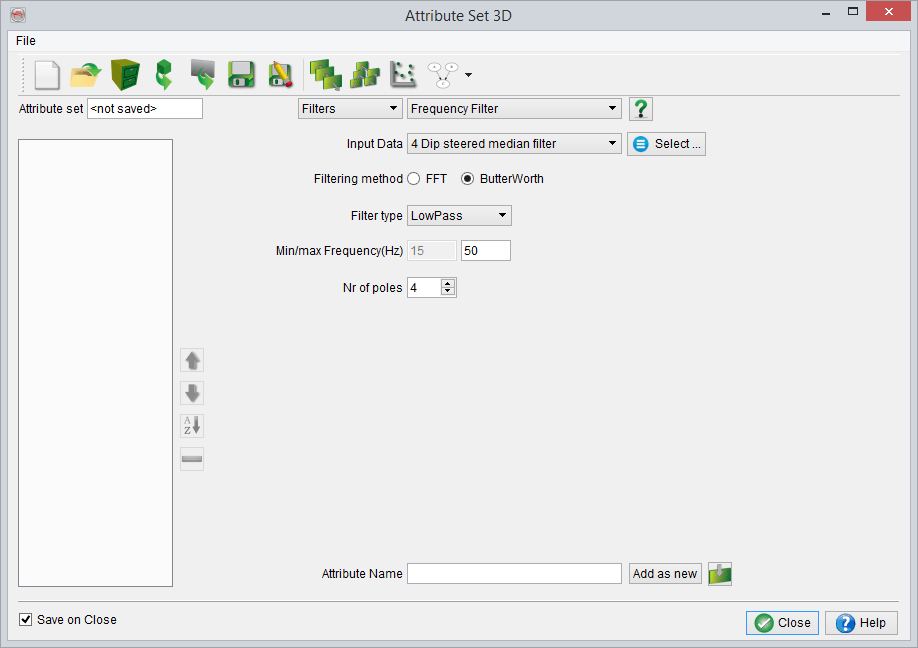
The difference between using the FFT or Butterworth filtering method is that, for the FFT, one considers the complete trace while for the Butterworth filter, only a "small" segment, depending on the selected number of poles, is taken into account. The user should keep in mind that using the Butterworth Filter results in a small shift in the seismic data.
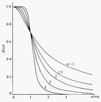
The curves of the Butterworth filter for various numbers of poles
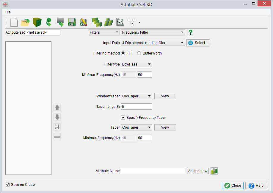
The Filter type is set to LowPass, HighPass or BandPass according as it is discriminating against frequencies above or below a certain limiting frequency or outside of a given band of frequencies. The top frequency tapering applied to the extracted data in the time domain.
Additionally, a frequency taper can be applied by setting the min/max Hz tapering window. This could be done by toggling Specify Frequency Taper ON. Press the View button to specify an appropriate frequency taper.
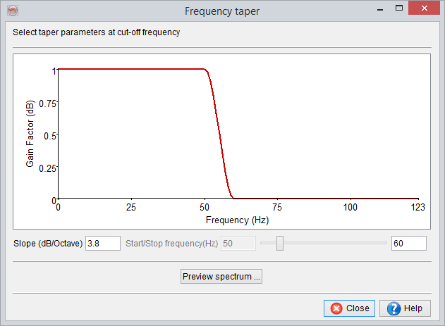
Frequency taper settings in the attribute definition (for filter type: 'BandPass').
Once the Frequency Taper is displayed (red line in a pop-up window), a spectrum on any inline/crossline can be viewed by pressing the Preview Spectrum button. It will prompt to select an inline/crossline ("Select line from Data"). In that dialog select either inline or crossline radio button and press Next. Sub select the part of inline/crossline and proceed. A blue coloured amplitude spectrum will be displayed (as shown below). Now adjust the parameters (Slope or Start/Stop Frequency) and finalize the frequency taper settings.

Interactive display of the frequency taper parameters (for filter type: 'BandPass').