11.13 Localized Velocity Fan Filter
Name
Velocity Fan Filter -- Attribute that returns energy with apparent velocities/dips inside a specified Min/Max range.
Description
The velocity fan filter passes energy with apparent velocities (for Time surveys) or apparent dips (for Depth surveys) inside the specified Min/Max velocity/dip range. The filter supports three options:
- pass low velocities/dips (i.e. suppress high velocities/dips)
- pass high velocities/dips (i.e. suppress low velocities/dips)
- pass velocities/dips within a specified cone.
Therefore, this attribute can be used to filter out or enhance certain dip/azimuth events.
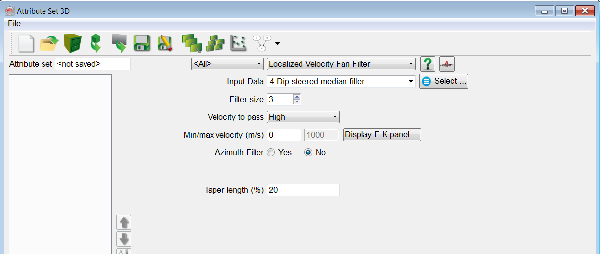
Input Parameters
The Filter size is the size of the 3D kernel. Filter size 3 means the data is convoluted with a 3x3x3 kernel. To reduce edge effects it is recommended to apply a cosine square taper. A Taper length of N means (100-2N)% of the specified velocity range will be flat. Azimuth filter is a special option that allows the dipping energy to be passed inside the specified Azimuth to pass direction only.
The different shapes of the filter ( low pass, high pass, interval velocity/dip) are shown below:
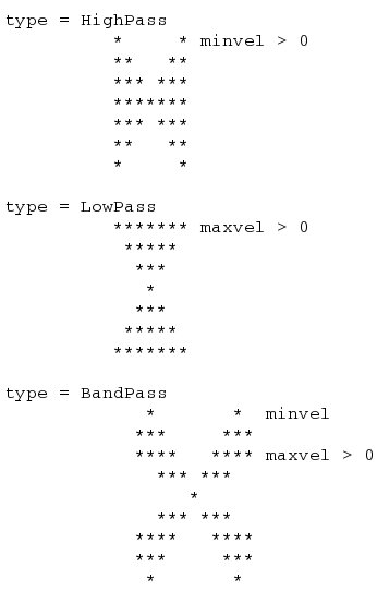
Note: Please be aware that in Time surveys, flat events have infinite velocity, and vertical events have a zero velocity. The opposite is observed in Depth surveys where not velocities but dips are used: Horizontal events have zero dip, while vertical events have 90 degrees dip.
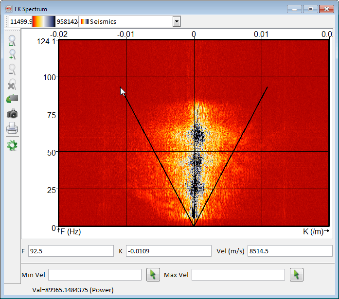
This option allows you to display a two-dimensional Fourier transform over time and space where F is the frequency (Fourier transform over time) and K refers to wave-number (Fourier transform over space).
Examples
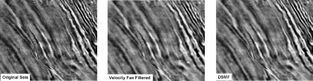
An example of a velocity fan filter (high-pass) applied on a time slice. By applying the appropriate filtering parameters, the random noise has been suppressed thus enhancing the amplitudes visibility. Also notice the comparison of this filter with the DSMF (Dip-Steered Median Filter) that is almost same with an assumption of high pass of velocities in the middle image.