2.2.3.2 Directional Lighting
![]() The directional lighting feature is used to illuminate the objects (displayed data) at a specific inclination (or dip angle) and azimuth. The feature controls the main headlight i.e. the intensity of the camera light and the intensity of the directional light. The dialog is launched by clicking the icon shown above.
The directional lighting feature is used to illuminate the objects (displayed data) at a specific inclination (or dip angle) and azimuth. The feature controls the main headlight i.e. the intensity of the camera light and the intensity of the directional light. The dialog is launched by clicking the icon shown above.
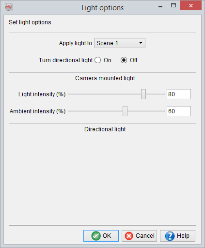
Directional light Dialog
The directional light dialog updates the scene instantly to reflect the changes made to the properties. If the OK button is clicked, the changes are retained, whereas, the Cancel button rules out all changes.
Apply light to: The directional lighting is independent for each scene, i.e the selected scene will be illuminated. However, selecting the option All in the drop down list will illuminate all scenes that are currently open.
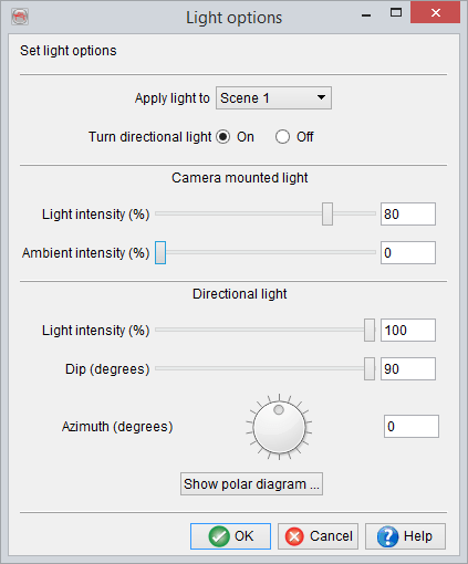
Camera mounted light: Use this slider to change the percentage of intensity of the camera light or the head light. 0% corresponds to total darkness while 100% corresponds to full intensity. Similar to the directional light dialog, the changes made to the azimuth and dip are instantly reflected in the selected scene(s).
Intensity: Sets the percentage of the intensity of the additional directional light. 0% corresponds to total darkness while 100% corresponds to full intensity.
Dip: This slider is used to set the dip value (in degrees) of the directional light. The directional dip is limited from 0 to 90 degrees.
Azimuth: This slider is used to set the azimuth (in degrees) value of the directional light. It can be any value from 0 to 360 degrees.
Show polar diagram: The azimuth and dip can be visualized using this diagram. This diagram can be used in combination with the sliders of the main dialog in order to position the directional light around the scene.
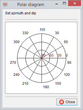
Polar diagram dialog
This is a dialog that displays the polar diagram for setting the azimuth and the dip values of the additional directional light. The location of the pointer (the red dot) determines the properties of the directional light. The pointer can be moved around by using the mouse within the polar diagram. The azimuth value can be read off the circumference of the outermost circle while the dip value is given by the location of the pointer along the radius of the circle.