4.3.11.1.1 SEG-Y Wizard
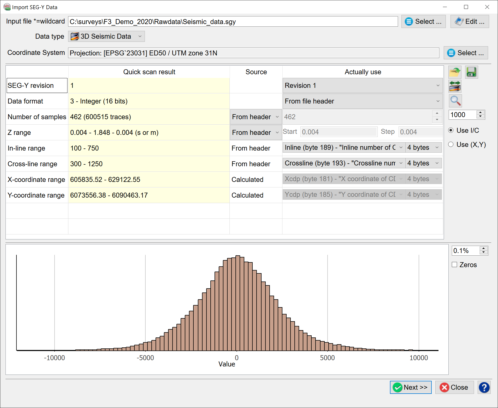
Generic Import SEG-Y Data wizard can be accessed by clicking on ![]() icon in the toolbar of main OpendTect window. The wizard supports import of 2D and 3D prestack and poststack data from one or multiple SEG-Y files. The layout of this window dynamically changes depending on the user choice of Data type.
icon in the toolbar of main OpendTect window. The wizard supports import of 2D and 3D prestack and poststack data from one or multiple SEG-Y files. The layout of this window dynamically changes depending on the user choice of Data type.
The generic wizard also supports import of zero-offset VSP data.
Data specific wizards are available via Survey > Import > Seismics > SEG-Y. The layouts are fixed for the data type selected via the menu (Data type option isn't available in these cases).
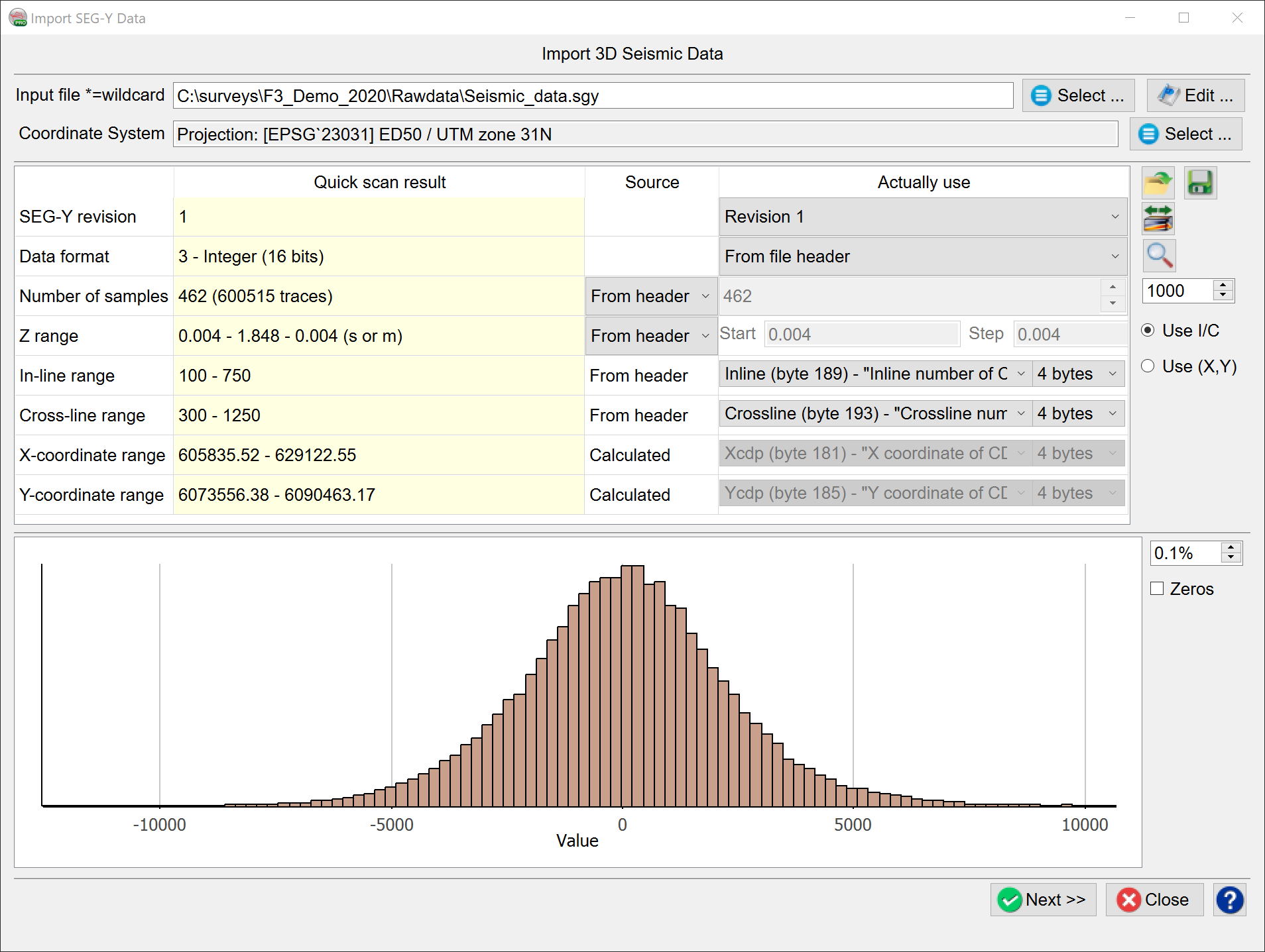
Input file(s): Select a SEG-Y file to import. In case of importing multiple 2D or 3D SEG-Y files select any of them first and then use the wildcard *.
Import 3D pre- or poststack data from multiple SEG-Y files: files must contain consecutive blocks of inlines and be indexed as filename_1.sgy, filename_2.sgy...
- Select one of the files;
- replace the file index by a wildcard * in the input field: filepath/filename_*.sgy
Import multiple 2D lines with pre- or poststack data: files must contain individual 2D lines and be indexed with the respective line names as filename_linename1.sgy, filename_linename2.sgy...
- Select one of the files;
- replace the line name by a wildcard * in the input field: filepath/filename_*.sgy;
- those parts of file names replaced by * are used as 2D line names (press Next and see that Line name option is greyed out and set to *).
Edit: (optionally) edit text, binary and trace headers of a SEG-Y file in Manipulate SEG-Y File window.
Data Type: the choice is only available in the generic Import SEG-Y Data window.
- 3D seismic data
- 3D PreStack data
- 2D seismic data
- 2D PreStack data
Coordinate System: When setting up a new project using a SEG-Y file, use this option to set the Coordinate Reference System for the project whilst importing the data.
Table: information required to import a SEG-Y file (therefore the table layout depends on the data type).
- Quick/Full scan result: shows results of a quick/full scan of a SEG-Y file:
- Quick scan: a partial scan of SEG-Y is performed upon file selection and after any change of SEG-Y import set-up.
- Full scan: press on
 icon to scan the entire file.
- Actually use: import parameters as confirmed/overruled by a user.
SEG-Y Revision (default = byte 301 of binary header): please refer to
- SEG-Y Rev. 0:
- SEG-Y Rev. 1:
- Data format, Number of samples, Z Range start/interval can be overruled.
- Data positioning (IL/XL, Trace/SP, X/Y and offset): standard byte locations are used.
- SEG-Y Rev. 2:
- File format options and standard trace header bytes are same as Rev.1.
Data format (default = byte 25 of binary header): (optionally) overrule data format.
Most header values and data samples are written using several bytes for each word/sample. Therefore knowing a correct byte order is a necessity. All SEG-Y standards (Rev. 0, 1 and 2) require using big-endian byte order. Occasionally one can run into data written using little-endian (reverse) one. Using standard SEG-Y data formats for reading such data results in unexpected scanned values of trace headers and unexpectedly large sample values (check the histogram). In this case use data formats with (byte swapped) option.
Number of samples (default = byte 21 of binary header / byte 115 of trace header): (optionally) overrule the number of samples per trace.
Z Range (units = seconds or meters).
- start (default = bytes 105 laga and 109 delrt of trace headers): (optionally) overrule start of Z-range (negative start is allowed).
- interval (default = byte 17 of binary header / byte 117 of trace header): (optionally) overrule Z-sampling (sampling rate).
OpendTect doesn't support import of a SEG-Y file with varying trace lengths (i.e. Z range start and interval must be constant for all traces in a file).
Data positioning:
Rev.1/Rev.2: trace header byte locations are standard, i.e. can't be selected by a user. If the file is wrongly tagged as Rev.1/Rev.2, over-rule it as 0 in Actually use column in order to be able to select non-standard trace header bytes.
3D poststack data is loaded based either on Inline/Crossline numbers or X/Y coordinates (see below Use I/C and Use (X,Y) options).
|
Rev.0 defaults |
Rev.1/Rev.2 hard-coded standard bytes |
|
| In-line range | 9 | 189 |
| Cross-line range | 21 | 193 |
| X-Coordinate range | 73 | 181 |
| Y-Coordinate range | 77 | 185 |
| Offset range (prestack only) | 37 | 37 |
2D poststack data is loaded based on trace numbers, reference numbers (SP) and X/Y coordinates.
|
Rev.0 defaults |
Rev.1/Rev.2 hard-coded standard bytes |
|
| Trace number range | 5 | 5 (can be over-ruled) |
| Shot-Point number range | 197 | 197 |
| X-Coordinate range | 73 | 181 |
| Y-Coordinate range | 77 | 185 |
| Offset range (prestack only) | 37 | 37 |
- Trace number range:
- In file: from a specified trace header byte.
- Generate: generate trace numbers by providing the number of the first trace in a 2D line and step in trace numbers.
Trace number must be unique for each trace along the line, therefore it can be either sequential trace number (byte 5) or CDP trace number (byte 21). A user is always allowed to select a non-standard byte even when the file is Rev.1.
2D and 3D prestack data additionally requires offset information.
- Offset range
- In file: from a specified trace header byte.
- From Src/Rcv (X/Y): calculate from source and receiver X/Y coordinates (standard byte locations are used: 73 and 77 for source, 81 and 85 for receiver).
- Generate: generate offsets by providing the offset of the first trace in a gather and step in offset values.
![]() Store this setup: save a SEG-Y import setup at the survey data root level.
Store this setup: save a SEG-Y import setup at the survey data root level.
![]() Use saved SEG-Y setup: retrieve one of the stored setups.
Use saved SEG-Y setup: retrieve one of the stored setups.
![]() Scan the entire input: updates Quick scan result with Full scan result of the entire input file.
Scan the entire input: updates Quick scan result with Full scan result of the entire input file.
![]() Examine input file: opens SEG-Y Examiner window for a specified Number of traces to examine (default=1000 traces).
Examine input file: opens SEG-Y Examiner window for a specified Number of traces to examine (default=1000 traces).
 (default = empty): (optionally) enter XY scalar to ignore scalco (byte 71 of trace header). X/Y coordinates are multiplied by this factor.
Note that scalco is the scale factor for all coordinate bytes with value plus or minus 10 to the power 0, 1, 2, 3, or 4 (if positive, multiply, if negative divide).
Histogram: displays a distribution of amplitudes after Quick (partial) or Full scan.
- Percentage clip for display (default=0.1%): amount of data in the histogram tails excluded from the plot.
- Zeros (default=unchecked): allows to include/exclude value 0 for histogram display.
Data specific options:
3D (pre- and poststack) data positioning can be based either on Inline/Crossline or X/Y coordinates of each trace:
- Use I/C (default): positioning of imported data is based on Inline/Crossline numbers, (X,Y) coordinates are therefore calculated from a survey setup.
- Use (X,Y): positioning of imported data is based on (X,Y) coordinates, Inline/Crossline numbers are therefore calculated from a survey setup. If Coordinate Reference System (CRS) is defined for the survey, CRS conversion will be available in the import window.
2D (pre- and poststack) data Z-range can vary per SEG-Y file if multiple lines of different vintages are imported at the same time:
- File Z's (available only when multiple 2D lines are imported): if checked, Z Rangestart/interval and Number of samples are used as they appear in each SEG-Y file.
Overruling of Z Range start/interval and Number of samples is possible only if File Z's is unchecked.