1.4 Thalweg Tracker
Introduction
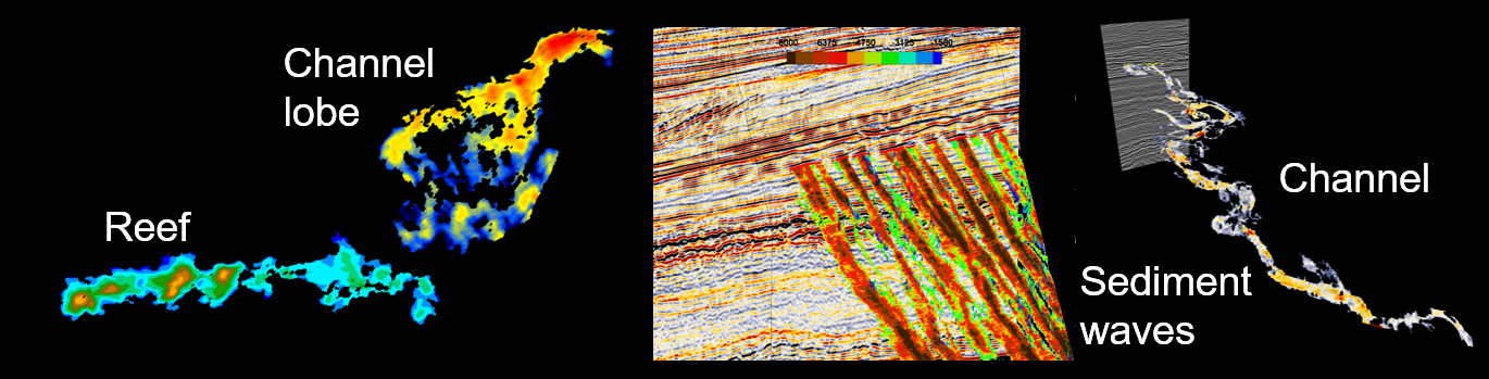
This plugin tracks seismic facies such as channels and reefs. It outputs either horizons with a set of tracking attributes, or 3D objects, or Pick sets.
A Thalweg is a geologic term to describe the path of a river as it flows through a valley (Thalweg is a German word; Thal means valley and Weg is path). A Thalweg tracker operates in a similar way: the tracker follows the path of least resistance.
The Thalweg tracker is a special form of a voxel connectivity filter. Based on certain user-specified constraints, It tracks neighboring samples in an input seismic cube. Initially the user picks a single seed position. The seed is considered to be a cube of unit size and the next sample to be tracked is chosen from all available samples along the ’faces’ of the seeds. In the first iteration, all six neighboring samples along the six faces of the initial seed act as candidates for tracking. Only the best matching position (i.e. the highest, or lowest amplitude) is added. In the next iteration, all samples neighboring the two currently accepted positions now act as candidates and again only the best matching position is added. This process continues until it is no longer possible to add candidates that meet the tracking constraints.
A Thalweg tracker adds only one position per iteration. If you choose to accept more than one position per iteration, the Thalweg tracker becomes a margin tracker. Thalweg and margin trackers are typically run sequentially.
The output of a Thalweg tracker is a Point Set that can be saved as "snapped" horizon (parameter window), or it can be saved as a 3D body. or Pick set (3D scene, right-click on the object). When it is saved as a horizon all tracking attributes will be saved as Horizon data with the horizon. The tracking attributes can be used for further analysis in the Crossplot tool.
Menu
![]()
Input cube: This is the input seismic (or attribute, impedance, ...) cube.
Area subselection: The tracking area (or volume) can be constrained using one of the many available criteria, viz. Range, Polygon, Horizon etc.
Start Position (Seed): This can be picked interactively with the green arrow. The picked amplitude is displayed immediately after picking.
Event to track: Samples can be tracked either on maximum, or minimum amplitude.
Thresholds and Layer Constraints: The automatic values for min and max thresholds are estimated from the picked position. These values can be overruled manually. When the Layer Constraints toggle is on the software will not allow a body to grow on traces where the body already exists. This (default option) prevents tracking multiple forks of an event.
Amplitude Scalar: This optional scalar is applied to the Amplitude attribute output and can be used to improve visualization.
Amplitude Sum Scalar and Amplitude Sum Step: The optional scalar is applied to the Amplitude Sum attribute output and can be used to improve visualization. The Amplitude Sum Step is the re-sampling rate that is used to compute the Amplitude Sum attribute (see Display options).
Schedule: This is the control center of the tracking process. The idea is that objects are tracked in one, or more sequential processing steps. Steps can be added with the green plus and red minus icons, respectively. Each step has its own parameters. Typically, the first step is run in Thalweg tracking mode, which means that only one cell per iteration is added. Only the best matching cell (the lowest, or highest amplitude of all neighbors) is added. In following steps the constraints can be lowered. More cells are added per iteration. This is the margin tracking mode.
A typical work flow is the following:
- First the Thalweg tracking mode is used to track a channel.
- Start by tracking a large number of positions. Let's say Max. Number of Cells is set to 20,000.
- Examine the result and observe (from the iterations attribute) where the body left the first Thalweg and spilled over into the next Thalweg.
- Re-track the object from the same seed position but now use a smaller number of points that will track the object until it reaches the spill-point. You have now found the first channel patch.
- To track the channel margins add another layer of let's say another 20,000 points but now accept more cells per iteration and accept more points than the best matching only.
- Save the tracked patch as a horizon.
- Repeat the process from another seed position and merge the patches (merge icon at the top of the window).
Max. Nr cells: This is the maximum number of cells that the body can grow with when Track is pressed.
Cells per iterations: This is the maximum number of cells that will be added per iteration, i.e. each time the neighbors are evaluated and the body grows. If set to one the tracker runs in Thalweg tracking mode. A value larger than one means margin tracking mode.
Cut-off criteria and Cut-off value: These constraints control which cells are acceptable when tracking in margin mode. A percentage cut-off of 5 means that the highest, or lowest 5% of all possible neighboring values are eligible. Out of this group the best matching cell is added first, followed by the next best and so on. This continues until either the number of cells per iteration is reached, or there are no more cells in the pool of eligible cells to add. The standard score criterion operates in the same way. The eligible neighboring values are the amplitudes above, or below the mean value of the body plus, or minus the number of standard deviations given in the standard score cut-off.
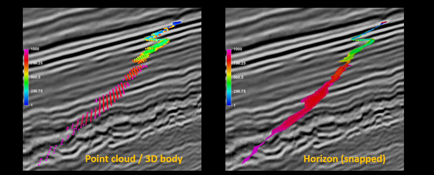
Track and View Log ...: Press track to actually run the tracker. Only the last step is processed. The output is shown in the 3D scene as a point cloud (left image below). Note that the point cloud is not saved! This is an interactive process. Play with the parameters until you are satisfied. Only then save the results: either as a horizon (right image below), or as a point set, or 3D object (in the 3D scene). Press View log to see the processing log file that prints statistics after each iteration.
Display and Output options
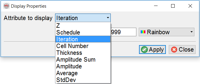
Attribute to display: Two sets of attributes are computed by the Thalweg tracker: Process attributes and Body attributes. The Process attributes tell us how the body and its properties grew from the seed position. Attributes in this group are: Schedule, Iteration, Cell Number, Average and StdDev. Schedule corresponds to the processing step in which the cell was added to the body. Iteration returns the iteration step that was reached when the cell was added. Remember that in margin mode more than one cell is added per iteration. The cell number is the sequential number assigned to the cell as the body grows. Average and StdDev are the running average amplitude and the running standard deviation of the amplitudes. These statistical properties vary as the body grows.
The Body attributes are: Z, Thickness, Amplitude Sum, and Amplitude. Z is the depth of the cell in 2WT, or depth, as the case may be. Thickness is the vertical thickness of the body. Amplitude sum is the vertical sum of the amplitudes computed from interpolated amplitudes with the user-defined sampling rate given in the Amplitude Sum Step field. Amplitude is the amplitude of the cell.
Output Horizon: The tracking results can be saved in the form of a Horizon. Typically, the horizon will be snapped to a maximum, or minimum event that is found within the user-defined search gate. All attributes will be saved as Horizon data with the new horizon. If the horizon was snapped, the amplitude attribute will return the amplitude of the snapped event.
Output 3D Objects, or Pick Sets: To save the results as OpendTect Pick set, or as 3D object, right-click on the point cloud in the 3D scene and use the corresponding menu option.
References:
Pelissier, M., Changhua Yu, Singh, R., Qayyum, F., de Groot, P. and Romanova, V. 2016. Thalweg Tracker: A Voxel-Based Auto-Tracker to Map Channels and Associated Margins. EAGE 78th EAGE Conference & Exhibition, Vienna, 30 May - 2 June 2016.
See also the pdf, and/or video recording of the oral presentation.