8.4.2 Model an existing line through well(s)
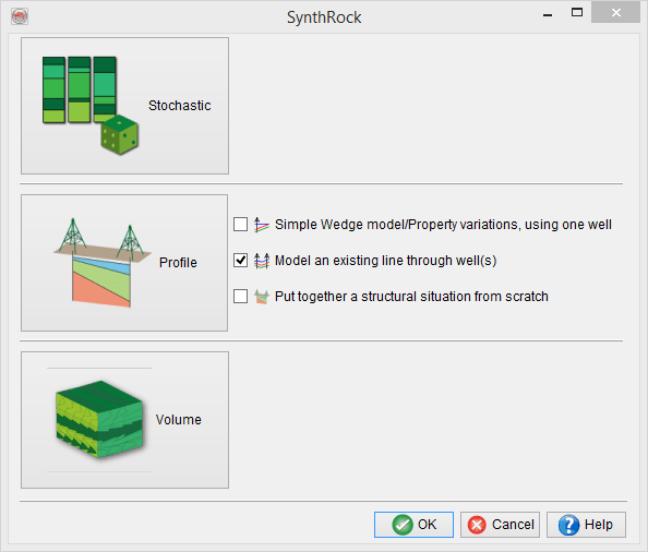
Model an existing line through well(s) is the second pre-defined workflow in SynthRock profile modeling which allows to quickly build a model through the existing wells in the project database. It is launched by checking the corresponding box in SynthRock start window and clicking OK.
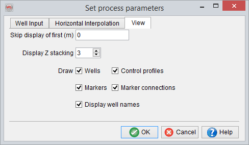
A user is expected to go through the pre-defined sequence of windows. The workflow starts, as any profile modeling in SynthRock, with setting modeling parameters in Set process parameters window and selecting properties to be modeled in Layer Properties - Selection window. Once the workflow is completed, both sets of parameters can be modified by clicking on the ![]() and
and ![]() icons of Layer modeling window respectively.
icons of Layer modeling window respectively.
In the example below, few changes of the default parameters are made in the first window in order to limit the modeled interval to [300 m; MMU].
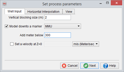
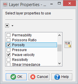
Porosity is added in addition to the default properties in the second window.
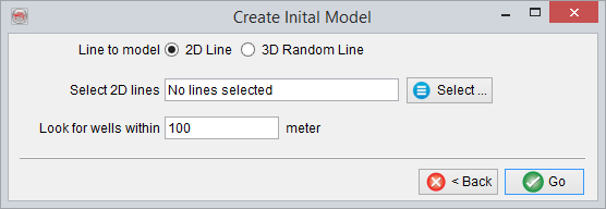
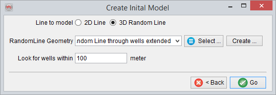
Once the modeling parameters and the property list are confirmed, Create Initial Model window appears. First, the Line to model option must be selected as either 2D line or 3D Random line.
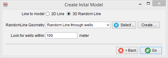
Create 3D Random Line
Geometry of a 3D random line through the existing wells can be created by clicking on Create button.
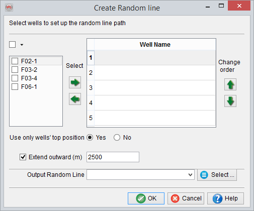
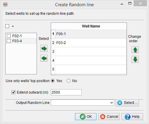
Wells to be used must be first selected and then added/removed using the 'Select' arrows. Order of the wells can be defined using the 'Change order' arrows and this order defines the shape of a random line. If Use only well’s top position is set to Yes, the random line is drawn through the well tops. Alternatively, No gives an option to choose Top or Bottom of each well. A random line can be optionally extended beyond the locations of the first and the last wells by checking the box and specifying the distance. Finally, after giving a name click OK to create the random line and return to Create Initial Model window.
Existing 3D Random line
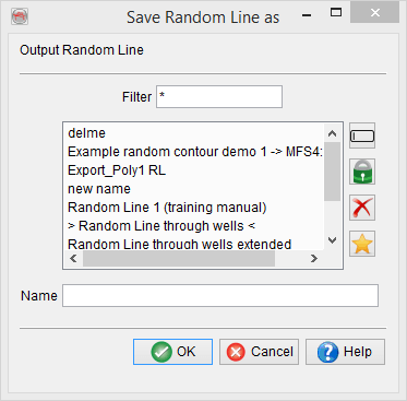
If a model is created along an existing 3D random line, click on Select button to choose from the list of existing random lines in the project database.
As an example, a model is created along a Random Line through wells extended which passes through all 4 wells, F06-1, F02-1, F03-2 and F03-4 and extends outwards on both sides.
Once the line is selected, its name appears in the Create Initial Model window. Look for wells within allows to include wells that are not positioned exactly on the selected line.
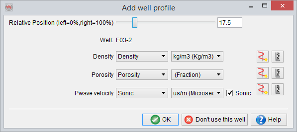
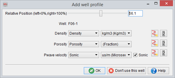
Click OK to proceed, and then go through a number of Add well windows. Such window is shown for every well located within the specified distance from the selected line. Automatically determined Relative Position and logs can be modified if needed. A user can also select not to use a particular well by clicking on Don’t use this well button.


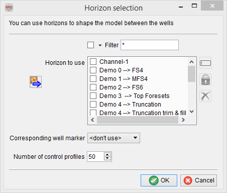
Next, the Horizon selection window allows to choose horizons and corresponding formation tops to steer the horizontal interpolation. Select any horizon in Horizons to use list and note that the Corresponding well marker is set to <don’t use> by default. This means that the selected horizon is not used in modeling.
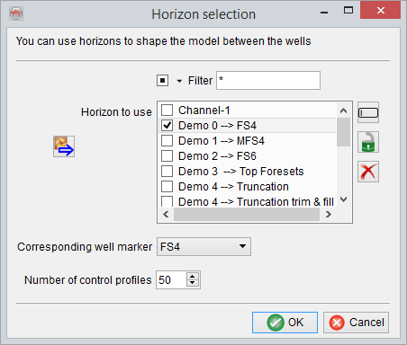
Select the first horizon to be used in the modeling and set the corresponding marker as shown below for ‘Demo 0 --> FS4’ horizon with a corresponding FS4 well top. Similarly, well tops have to be selected for all the horizons to be used in the modeling. Finally, Number of control profiles can be specified. Clicking OK generates a model with default number of pseudowells.
At this point the pre-defined workflow is finished, and further modeling can be continued using the classic Profile mode functionality in Layer modeling window.
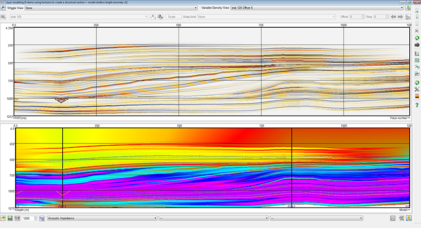
An example below shows the final model along the Random Line through wells extended. Five horizons and corresponding well tops are set as following: ‘Demo 0 --> FS4’ - FS4; ‘Demo 1 --> MFS4’ - MFS4; ‘Demo 4 --> Truncation’ - Truncation; ‘Demo 5 --> FS7’ - FS7; and ‘Demo 6 --> FS8’ - FS8. Note, that default number of pseudowells is changed to 1200, and some display parameters are modified to create this image. The green line overlying synthetic seismic corresponds to FS8 well top.
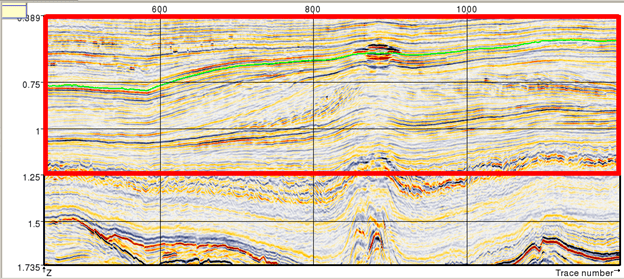
Below is the corresponding seismic section along the selected random line. The red box outlines the modeled interval, and the light green line corresponds to ‘Demo 6 --> FS8’ horizon. The constructed model is a good start for further detailed modeling. The detailed modeling can be done to support existing interwell interpretation. For example, by modifying properties of the control profiles in the vicinity of the high-amplitude anomaly seen in the middle of the seismic section along the green horizon.
Existing 2D line
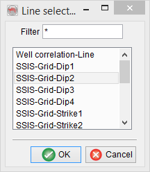
Switch Line to model to 2D line option and click Select. In the Line selection window choose the existing 2D line in the project database along which modeling is to be done.
Once the 2D line is selected, specify the appropriate distance from the line to include all required wells for the modeling and click OK. Afterwards, follow the instructions described for Existing 3D Random line.