8.5.2 Fluid Replacement Parameters
Once a fluid column has been defined in the pseudo-wells, the fluid replacement can be carried out by specifying the parameters for the Gassmann's equation.
Define Fluid Replacement Parameters
Click on ![]() from the vertical list of icons on the right side pane, in the layer modeling window, to specify the fluid replacement parameters for various layers with fluid content.
from the vertical list of icons on the right side pane, in the layer modeling window, to specify the fluid replacement parameters for various layers with fluid content.
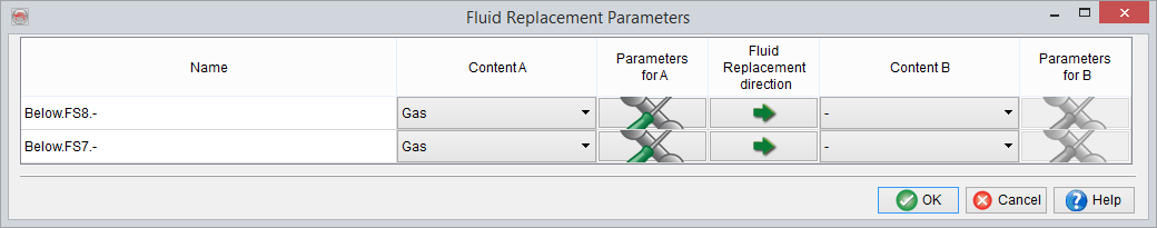
Here, the user can specify, for various layers, the fluid Content A (initial) and the fluid Content B (after replacement). The parameters for individual fluids before/after replacement are specified by clicking on the![]() icon. Now, in the above example, the initial fluid content in the two intervals (below the two well markers) is brine and is denoted by a '-' sign, by default. As the initial fluid content A is brine, the parameter specification icon has grayed out. The final fluid content, B, is gas and therefore clicking on the above mentioned icon, pops-up the following window. It should be noted that the direction of fluid replacement is from brine to gas, the direction can be changed by clicking on the
icon. Now, in the above example, the initial fluid content in the two intervals (below the two well markers) is brine and is denoted by a '-' sign, by default. As the initial fluid content A is brine, the parameter specification icon has grayed out. The final fluid content, B, is gas and therefore clicking on the above mentioned icon, pops-up the following window. It should be noted that the direction of fluid replacement is from brine to gas, the direction can be changed by clicking on the![]() : this will also change the direction of the arrow.
: this will also change the direction of the arrow.
Fluid Replacement Parameters per unit
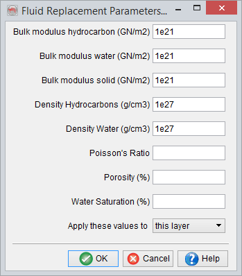
The top five parameters have to be filled in. If the Poisson's Ratio, Porosity and Water Saturation information is available in the layer model, they can be left blank. In absence of this information, a constant values can be filled in for these three parameters. Finally, these parameters can be defined for the layer in consideration, similar layers or all the layers having fluid content defined.
Apply Fluid Replacement
Now, once the fluid replacement parameters have been defined, the ![]() icon can be pressed to apply the fluid replacement. This will update the elastic properties (e.g. Vp, Vs, Density etc.) of the pseudo-well layers with fluid content, which will in turn impact the synthetic seismic response.
icon can be pressed to apply the fluid replacement. This will update the elastic properties (e.g. Vp, Vs, Density etc.) of the pseudo-well layers with fluid content, which will in turn impact the synthetic seismic response.
When the aforementioned icon is pressed the first time, the user has to specify various rock properties defined in the pseudo-wells, as required by the Gassmann’s fluid replacement algorithm. They are Vp, Vs, Density, initial Water Saturation, final Water Saturation and Porosity.
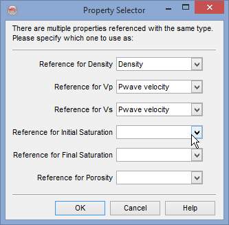
If only fluid type is changed, while keeping a constant water saturation, e.g. oil to gas (at constant Sw = x) or from oil/gas (at Sw = x) to brine (i.e. Sw = 1) same water saturation property should be specified as reference for initial and final saturations. If the final saturation is kept empty, the software automatically uses the initial saturation as final saturation as well. It is also possible to specify constant values of initial and final water saturations as well as porosity, in the Fluid Replacement Parameters dialogue. If that is done, any references defined for saturations and porosity in the above window will not be honoured.
However, if the target is to compute elastic properties at different water saturations with/without changing the fluid type, e.g. oil (at Sw = x) to oil (at Sw = y) or oil (at Sw = x) to gas (at Sw = y), one needs to specify separate initial and final saturations. Note that in order to do so, two layer properties of the same type (i.e. Volumetrics → Water Saturation) need to be predefined in the Manage Layer Properties and selected in the simulation in question.
For shaly sands, use effective porosity and effective saturations, in the fluid replacement.
Below is an example of water saturation modeling, based on F03-4 well of F3 Demo data-set, wherein a gas column of thickness 30m is attached below the FS8 marker. Here modeling is done to decrease the logged water saturation from 100% to 90%, from left to right to replace with gas (i.e. gas saturation increases from 0% to 10%). Afterward, fluid replacement is applied to compute the change in seismic response corresponding to the change in fluid fill.
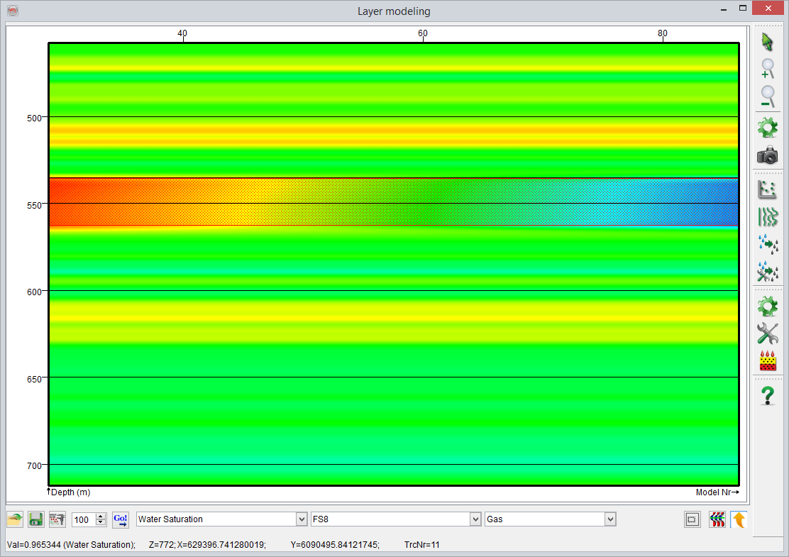
Example profile of water saturation variation from 90% to 100%, from left to right
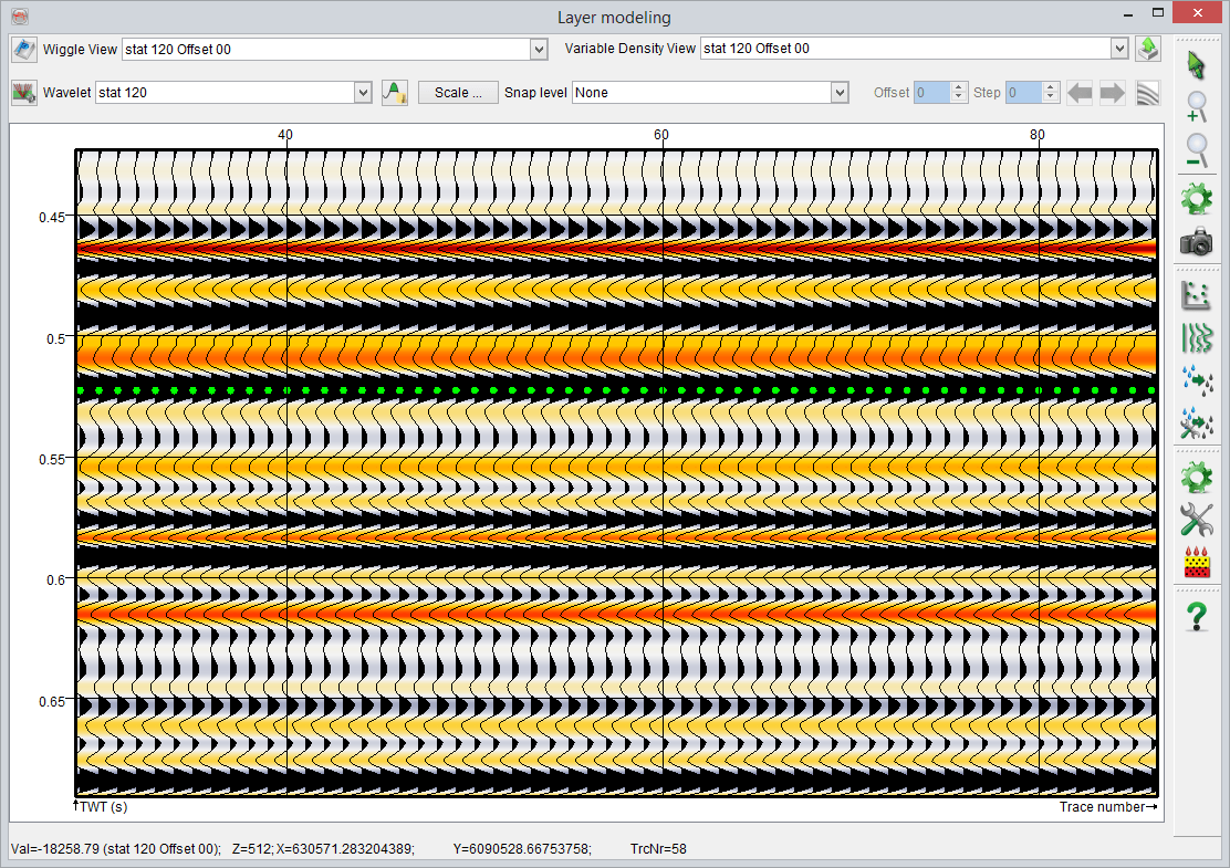
Original synthetic seismic, corresponding to fully brine case (i.e. water saturation of 100%)
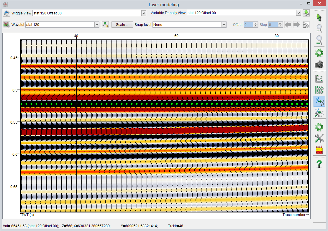
Synthetic seismic after replacing brine with gas, corresponding to varying water saturation from 90% to 100%, left to right