4.3.11.1.2.3 SEG-Y Import
Import SEG-Y window layout depends on the user-selected SEG-Y Revision.
Rev.1
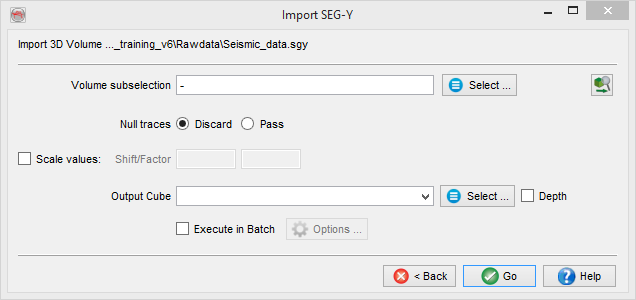
If the file is Rev 1 standard then the import is almost complete: You must provide an output name and can optionally sub-select a range of the volume to be loaded and/or change the output format and/or re-scale the amplitudes. Pressing Go will launch the import.
Depth volumes can be imported in time surveys and vice versa by using the depth/time toggle. They can be visualized using transformed scenes, providing that velocities are available.
![]() Pre-scan file(s): launch a partial or a full SEG-Y scan.
Pre-scan file(s): launch a partial or a full SEG-Y scan.
Mostly Rev.1
If the file is mostly Rev 1 but with changed parameters you will receive three additional fields that can overrule the values to be found in the headers:
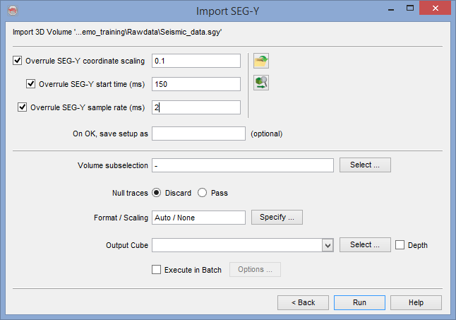
- Overrule SEG-Y coordinate scaling: all trace coordinates are multiplied by this scalar.
- Overrule SEG-Y start time/depth (units: ms, m or ft): time/depth of the first sample of the traces (can be negative).
- Overrule SEG-Y sample rate (units: ms, m or ft): provide the data sampling rate.
Those parameters constitute a SEG-Y setup that can be saved and retrieved using the yellow folder icon on the right. This setup will not only contain the parameters but also the path of the input files and settings of the preparation step. The setups are data dependent therefore they are stored in your survey.
Not Rev.1
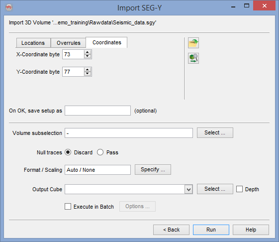
If the file is not Rev 1 you will get the overrule fields described above in a tab and two additional tabs to provide the byte locations of either the pair inline/crossline or the pair of X and Y coordinates. In the case of prestack data an additional tab will be present to provide the offsets/azimuth byte locations.
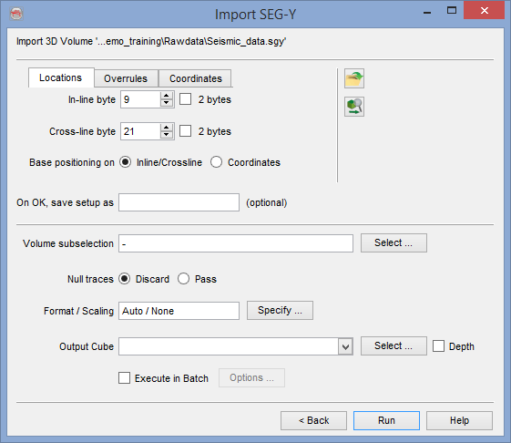
You need to look at the trace headers in the examine window and assign the correct settings in this import window. Once again the entire import setup may be saved or retrieved. Once this is done you must provide an output name and can optionally sub-select a range of the volume to be loaded and/or change the output format and/or re-scale the amplitudes. Pressing Ok will launch the import.
The import of 2D lines is somewhat different: Inlines and Crosslines are replaced by trace numbers, that must be unique for each trace (therefore it can be the CDP but not the Shot Point).
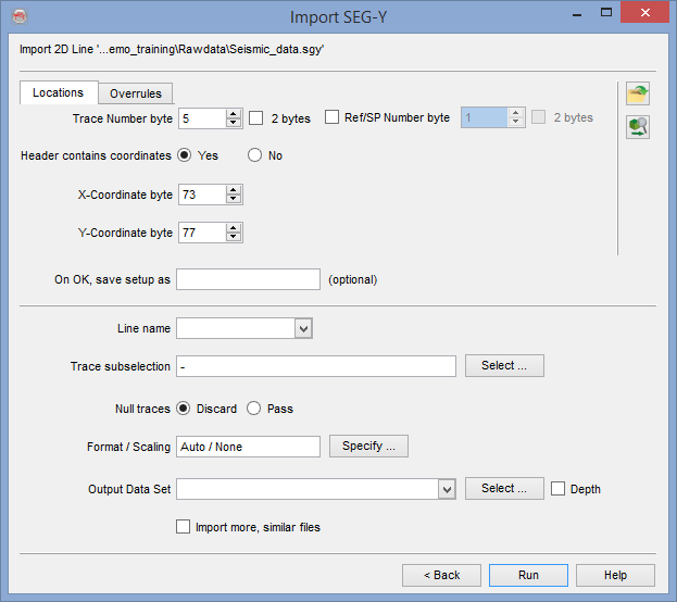
Coordinates can be imported from one auxiliary file or specified manually and generated during import coordinates if missing or wrong in the trace headers (see below on the right hand-side). This can be done by toggling off the X-coord byte field.
Generate XYs
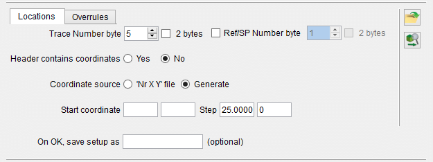
The coordinates are generated for each trace position by providing the X and Y coordinates of the first trace, and a regular step in both directions. Units to be used are the same as specified in the survey definition.
Input Auxiliary file
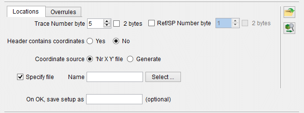
Optionally the coordinates can be specified using an auxiliary file. The format should be an input ascii file with one position per line in a fixed column format without header: File column should have the trace number, second column the X coordinate, third column the Y coordinate. Units to be used are the same as specified in the survey definition.
The line name is most often part of the input file name. It will be used only if a single line is loaded. Otherwise the line name is extracted as a part of the filename (see further below).
The Output data set name represents a 2D survey that comprises one or more lines. An OpendTect survey can have many 2D surveys (data sets), that are group of 2D lines that can be selected together for processing and interpretation.
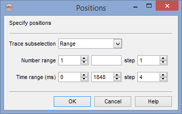
There is no format/scaling for 2D lines. The SEG-Y data format defines the OpendTect format. However, there is a trace sub-selection option to select either a trace "Range" or "All".
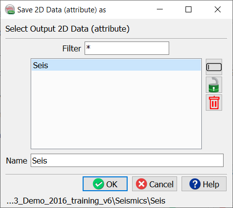
A default attribute name "seis" will be given to each line of the loaded data set. This can be changed by pressing "Select" and filling the empty "Attribute" field, like in the example below:
Multiple 2D lines loading must be enabled using the button "Import more, similar file" on the last line before pressing "OK". Any line can be used to go through the wizard, and the settings must be the same for all lines. If that is not the case then it is best to run the wizard several times per group of lines of similar SEG-Y settings.
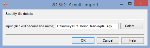
This additional window is used to specify the generic line name out of the SEG-Y filenames. The line name must be replaced by "#L", while everything else (including the path and the extension) is shown as text, like in the above example:
$DATAPATH/Line_#L.sgy
There will be one progress bar per input file during loading.
It is a good practice to display the 3D seismic data on a z-slice to check for any gaps in inline/cross-lines or null traces, after importing it.