3.4 Random Line
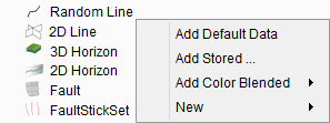
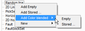
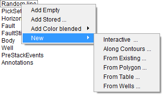
If you click on the Random line in the tree, four options will be available: Add Empty, Add Stored, Add Color blended and New.
With multiple nodes, the random line can also consist of multiple flat sections. The sections of one single random line may intersect one another. In interact mode, the little plane of a node can be used to drag the node laterally, and the vertical tube can be used to shift the edge of the random line vertically. Nodes can be added from the pop menu by right clicking on the random line in the Interact mode.
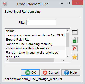
Add Stored: Select from a list of (previously stored) random lines to display it in the scene.
Add Color blended: A color blended Random Line may be added. This may be either a color blended version of a previously-stored random line, or an 'Empty' color blended random line:
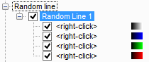
RGB(A*) color-blended attribute display is used to create a normalized color-blended display that often show features with greater clarity and enhances a detail map view. Though traditionally, it is used to blend the iso-frequency responses (Spectral Decomposition), RGB(A) can also be used to blend three or four different attributes that define a comparable spectrum. For instance, spectral decomposition outputs the amplitude at discrete frequencies. So, it renders the same output (unit=amplitude). Depending upon a geological condition or the objective, FFT short window or CWT (continuous wavelet transform) can be chosen.
* Once you have your inputs selected for the appropriate color attributes, it is also possible to add a fourth attribute (the 'A' or 'Alpha channel') to highlight structural features such as faults/fractures (ie: add a similarity attribute).
New: There are several ways to create a new random line:
Use in HorizonCube creation, when it is created in a 2D line-section that follows the well paths.
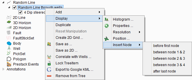
When right-clicking on the newly created random line, the following options are available in a pop-up menu:
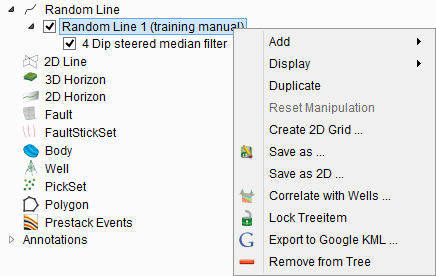
Add
- Add attribute: When selected, choose to display data from stored cubes, from an attribute from the current attribute set or from an output node of the current neural network. To display an attribute or neural network, select or create an attribute set or neural network first.
- Add Volume processing attribute: Display volume created from the volume builder
- Add HorizonCube display: Display the stored HorizonCube
- Add System tracts display: This option will add systems tract interpretation.
Display:
- Histogram: Displays multiple histograms for the randomline. If there are more than one attributes displayed, it will show the histograms of each in a pop-up view.
- Resolution: Choose the resolution between standard/higher/highest
- Position: It is used to manipulate the nodes / position of a random line. To read more, please go to the
- Insert node: Insert a new node before the selected node.
- Properties: This option refers to display parameters such as Ambient reflectivity, Diffuse reflectivity, Transparency.
Duplicate: Duplicate the line as an empty element in the tree. This option displays different attributes on the duplicated line whilst keeping the original data.
Reset Manipulation: This will reset any change in the position of the random line (or its nodes) that you have applied and it will set line to its original position. This option is only available if changes have been made to the position of the element.
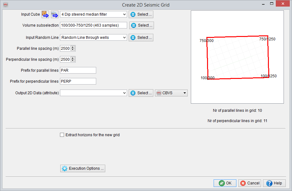
Create 2D Grid: The random lines (with two nodes only) can be used to create a 2D grid with a fixed grid spacing. When selected, the Create 2D Grid window is launched (see below). Here, specify the input 3D seismic volume and the output data set name. The output grid is generated according to the dip (parallel) and strike (perpendicular) direction of the selected random line. The prefix labels are used as prefixes to the output line names, stored to the specified new data set name. The grid spacing is the constant spacing between the two lines. At the bottom, the total number of parallel and perpendicular lines will be updated according to the grid spacing. By pressing OK, a batch process will start to generate the 2D grid. When the batch program is finished, the data can be displayed in the scene (see
Save As: Save the random line as a new name or overwrite the existing.
Save As 2D: Creates a 2D line from a Random line. Right-click on the random line in the tree and select Save As 2D. A window will pop up, as shown below. Select the Input cube, the output line and the line name. The first trace nr number of line is also necessary.
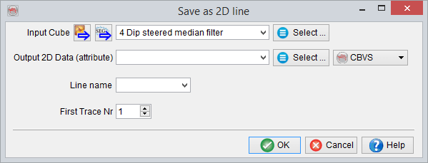
The survey type should be 2D as well if you want to view the 2D line created from a random line.
Correlate with wells: This option is used to correlate a random line with wells. Well - seismic correlation is normally done in the Well Correlation Plugin (WCP), which requires a commercial license.
Lock: Locks the selected object. This will prevent accidental removing, moving or displaying data on the object. After clicking lock again, editing is again enabled.
Export to Google KLM: Export selected random line to a Google KML file. Specify the KML file parameters in the pop-up dialog.
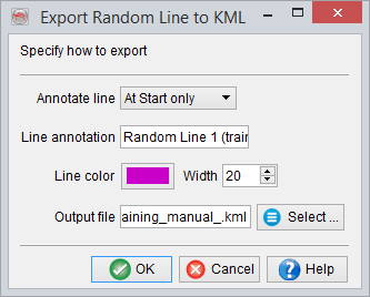
Annotate the start and end of the random line with a user defined line annotation in the output file settings.
Remove: Remove the random line from the tree and the scene. Do ensure to first 'Save' (any changes to) the random line before removing it.
The options available for attribute pop-up menu list are briefly described here:
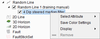
Select Attribute: When selected, data can be displayed from stored cubes or an attribute from the current attribute set (if available). To display an attribute, select or create an attribute set first.
Save Colour Settings: Save color settings for a specific stored volume and make them available for later use.
Move: Move the attribute up, down, to top of the list, or to bottom of the list.
Display: There are several display settings / features that are briefly explained below:
- Show Histogram: Display data statistics (selected attribute) of the randomline as a histogram in a pop up window.
- Show Amplitude Spectrum: Amplitude vs frequency plot will be shown in pop up window.
- Change transparency: Change the transparency of the attribute item to view one or more overlaying attributes simultaneously.
- 2D Viewer - VD / Wiggles: Display the selected attribute in the 2D viewer as "Wiggle" or "VD" (Variable Density). For more details, please refer to: 2D viewer
Remove: Removes the attribute item from the tree.